

Dental drill system and method of use
- Summary
- Abstract
- Description
- Claims
- Application Information
AI Technical Summary
Benefits of technology
Problems solved by technology
Method used
Image

Examples
first embodiment
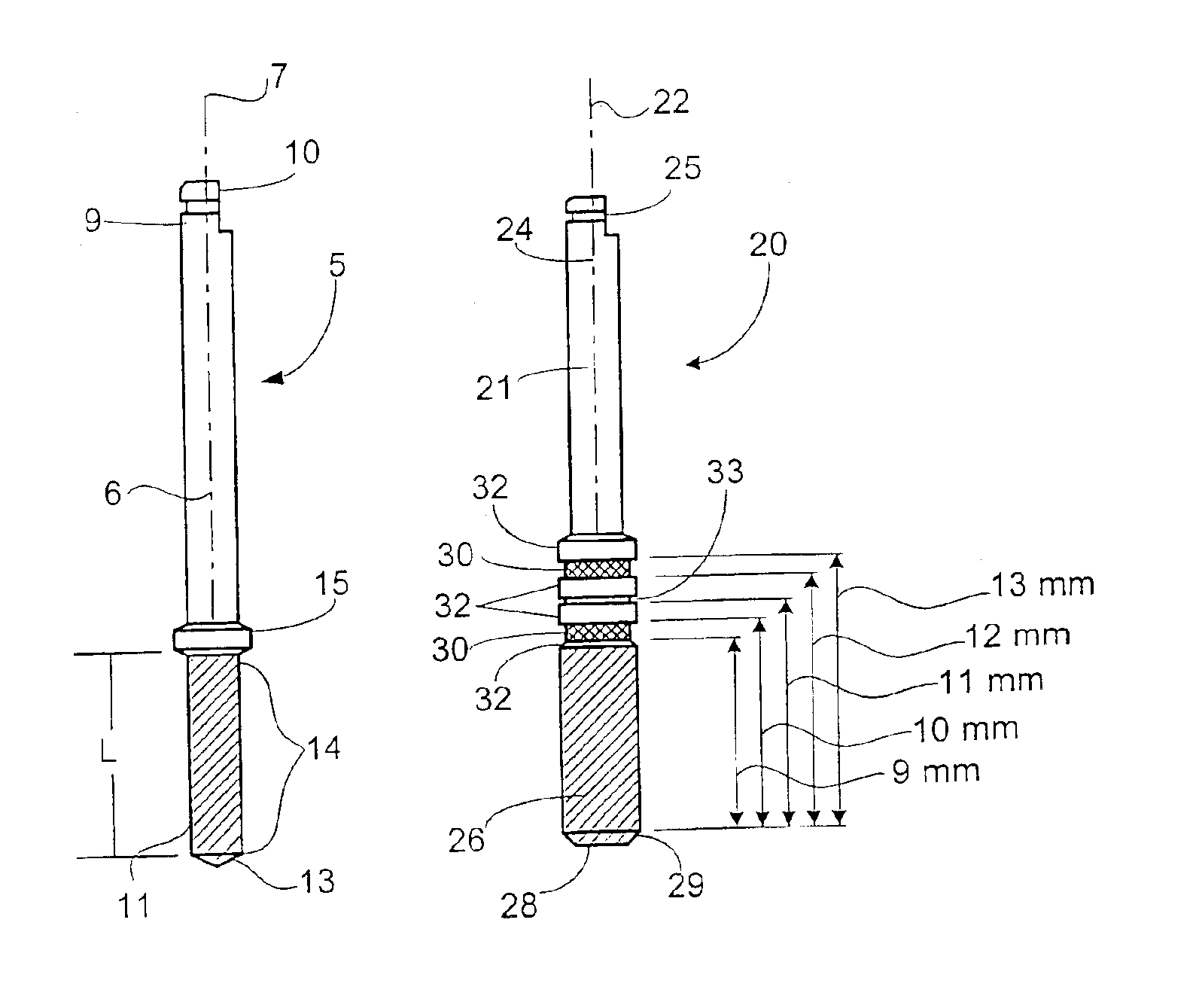
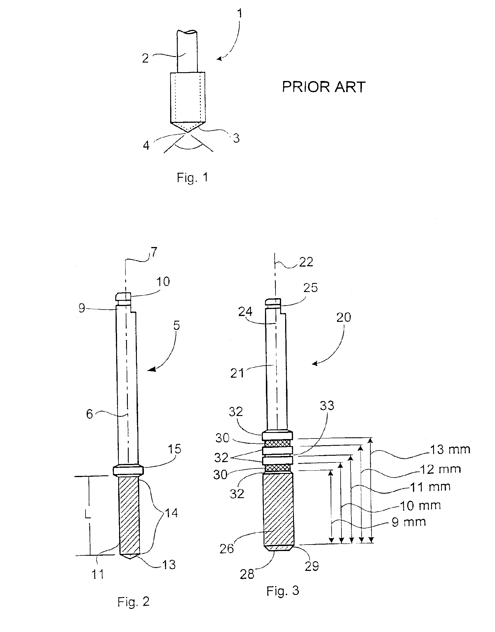
Referring now to FIGS. 3 and 8, a width increasing drill 20 of the dental drill system is illustrated. The width increasing drill has an elongate body 21 formed about a longitudinal axis 22, with a first end 24 at which a conventional right angle latch or chuck 25 is formed. Although a right angle latch is illustrated, as known to those of skill in the art, any known type of latch, chuck, or drive connection may be used in place of the right angle latch or chuck, as desired, for any of the several embodiments of the depth and width increasing drills of the invention. So constructed, the right angle latch, or other drive connection, for both of the depth and the width increasing drills can be readily affixed to any of the known types of dental drill handpieces currently in use, and as may be developed in the future.
The width increasing drill 20 has a second end 26, at which a flat, a straight, or a “blunt” drill tip 28 is defined. The cutting geometry 29 of the drill tip is defined a...
second embodiment
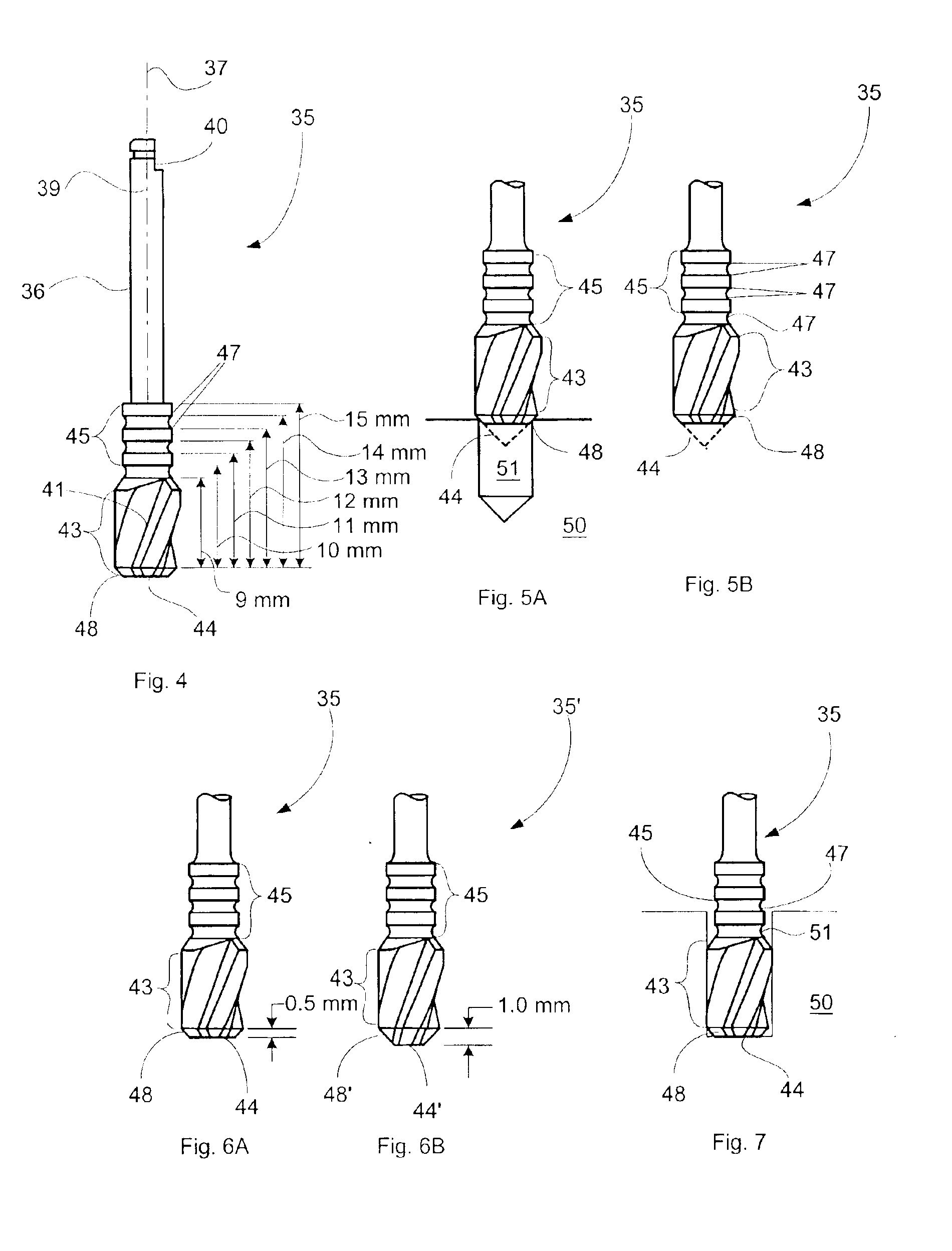
a width increasing drill 35 of the dental drill system is illustrated in FIGS. 4 through 7. The width increasing drill 35 has an elongate body 36 formed about a longitudinal axis 37, with a first end 39 at which a conventional right angle latch or chuck 40, or other desired drive connection / construction, is formed. The width increasing drill 35 has a second end 41, at which a flat drill tip 44 is defined.
A cutting geometry 43 is defined about the exterior periphery, and at the second end of the drill, i.e., the drill tip, extending in the lengthwise direction thereof, and is constructed as described herein such that the width increasing drill acts to remove material only from the sides of the osteotomy opening, and not to otherwise increase the depth of the osteotomy, as discussed above. The cutting geometry 43 can again be of any desired and / or conventional cutting geometry, for example it may comprise a spiral, a helical, or a spade bit, or any other known type of cutting geometry...
third embodiment
the width increasing drill 20′ is illustrated in FIG. 8. The width increasing drill 20′ is formed identically to the width increasing drill 20 described above, with the exception that the diameter of the width increasing drill 20′ is progressively greater than that of the drill 20. A third embodiment of a width increasing drill 75 is also illustrated in FIG. 8. Referring now to FIG. 8, the width increasing drill 75 has an elongate body 76 formed about a longitudinal axis, with a first end 77 at which a conventional right angle latch, or chuck, or a suitable or drive connection 78 is formed. The width increasing drill 75 also has a second end 79 at which a flat blunted drill tip 80 is defined.
As for the other embodiments of the width increasing drill 20, 35, respectively, the width increasing drill 75 also has a series of spaced and recessed annular depth grooves 82 extending in the lengthwise direction of the drill body, each depth groove being formed in and about the drill body at ...
PUM
 Abstract
Description
Claims
Application Information