Prosthetic foot having shock absorption

a technology of prosthetic feet and shock absorption, which is applied in the field of prosthetic feet, can solve the problems of less dynamic devices, dampening the energy return response, and inefficient transfer of energy of heel strikes to the toes, and achieve the effect of absorbing energy and efficiently transferring energy

Inactive Publication Date: 2005-03-08
THE OHIO WILLOW WOOD CO INC
View PDF20 Cites 84 Cited by
  • Summary
  • Abstract
  • Description
  • Claims
  • Application Information

AI Technical Summary

Benefits of technology

It is an object of the present invention to provide a prosthetic foot which can absorb energy on heel strike and efficiently transfer the energy to the toe of the prosthesis for use during toe-off.

Problems solved by technology

However, this conventional design has a number of problems.
For these reasons and because the toe spring is supported by the telescoping pylon, the pylon tends to remain compressed until after toe off, and so the energy of the heel strike is not efficiently transferred to the toe spring for use during toe-off.
Since the toe spring and the telescoping pylon are acting in series when the toe is loaded, the telescoping pylon can dampen the energy return response of the toe spring, making the device less dynamic than desired.
Also, since the toe portion of the prosthesis is mounted exclusively to the telescoping pylon, the height of the prosthesis may be excessive, and the apparent length of the user's leg will vary markedly during walking—an unnatural and undesirable tell-tale of the presence of the prosthesis.

Method used


Image

  • Prosthetic foot having shock absorption
  • Prosthetic foot having shock absorption
  • Prosthetic foot having shock absorption

Examples


first embodiment

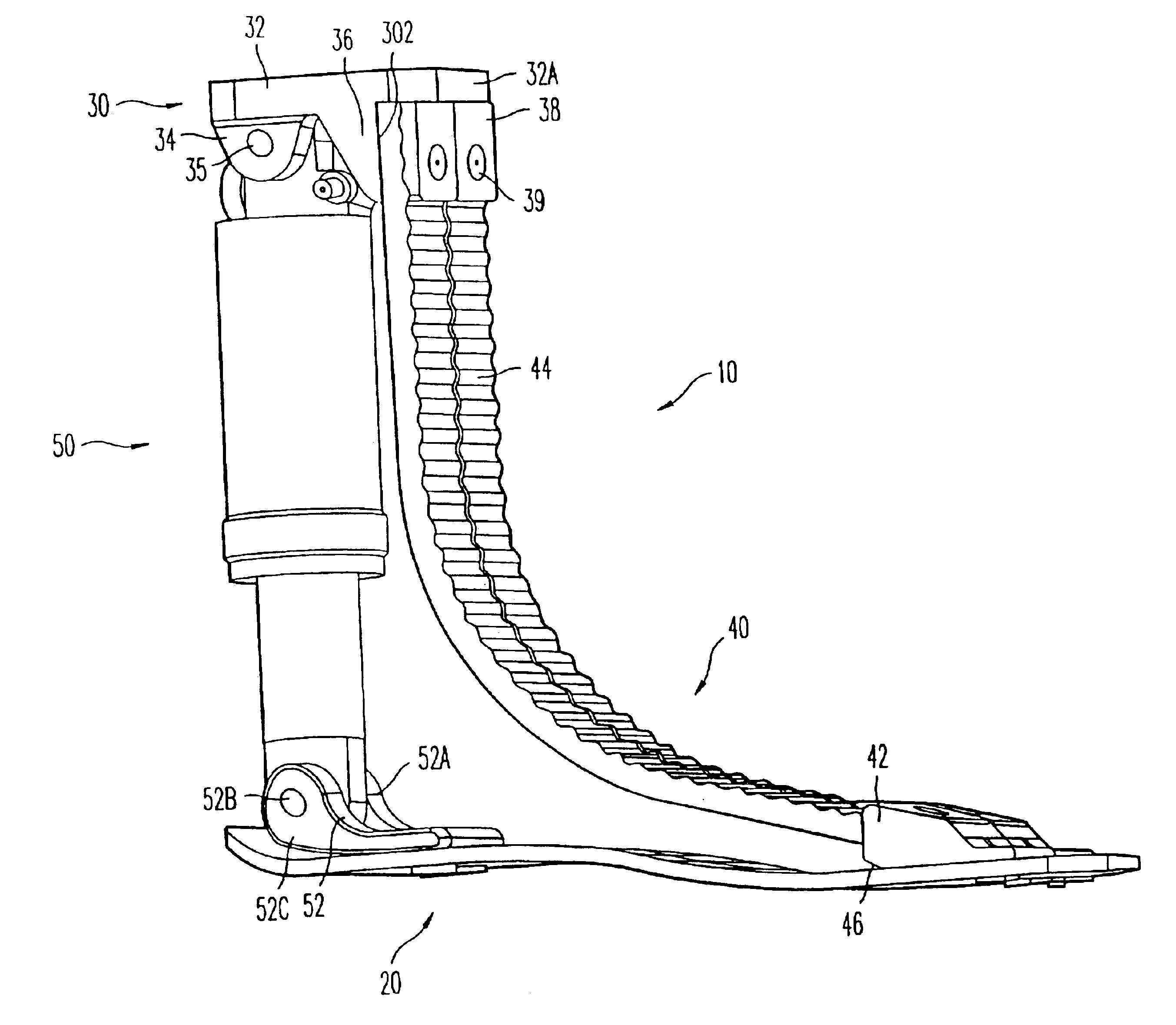
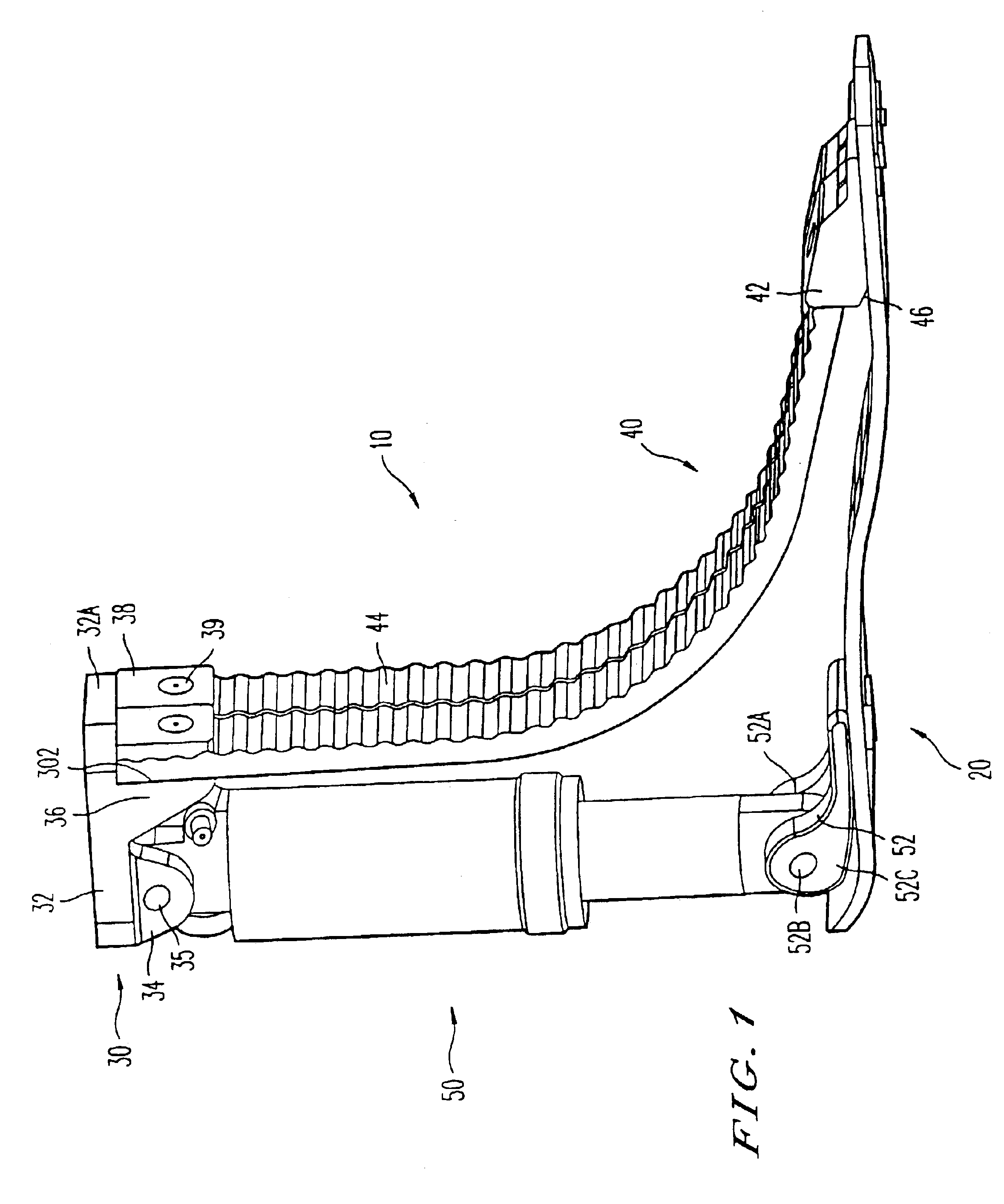
Referring now to the drawings wherein like reference numerals designate identical or corresponding parts throughout the several views, according to the invention illustrated in the non-limiting FIGS. 1 and 2 of the drawings, and in particular the variant of FIG. 1, the main components of a prosthetic foot 10 comprise contoured foot plate 20, a top adapter 30, a pair of toe springs 40 and a heel spring / shock absorber 50.

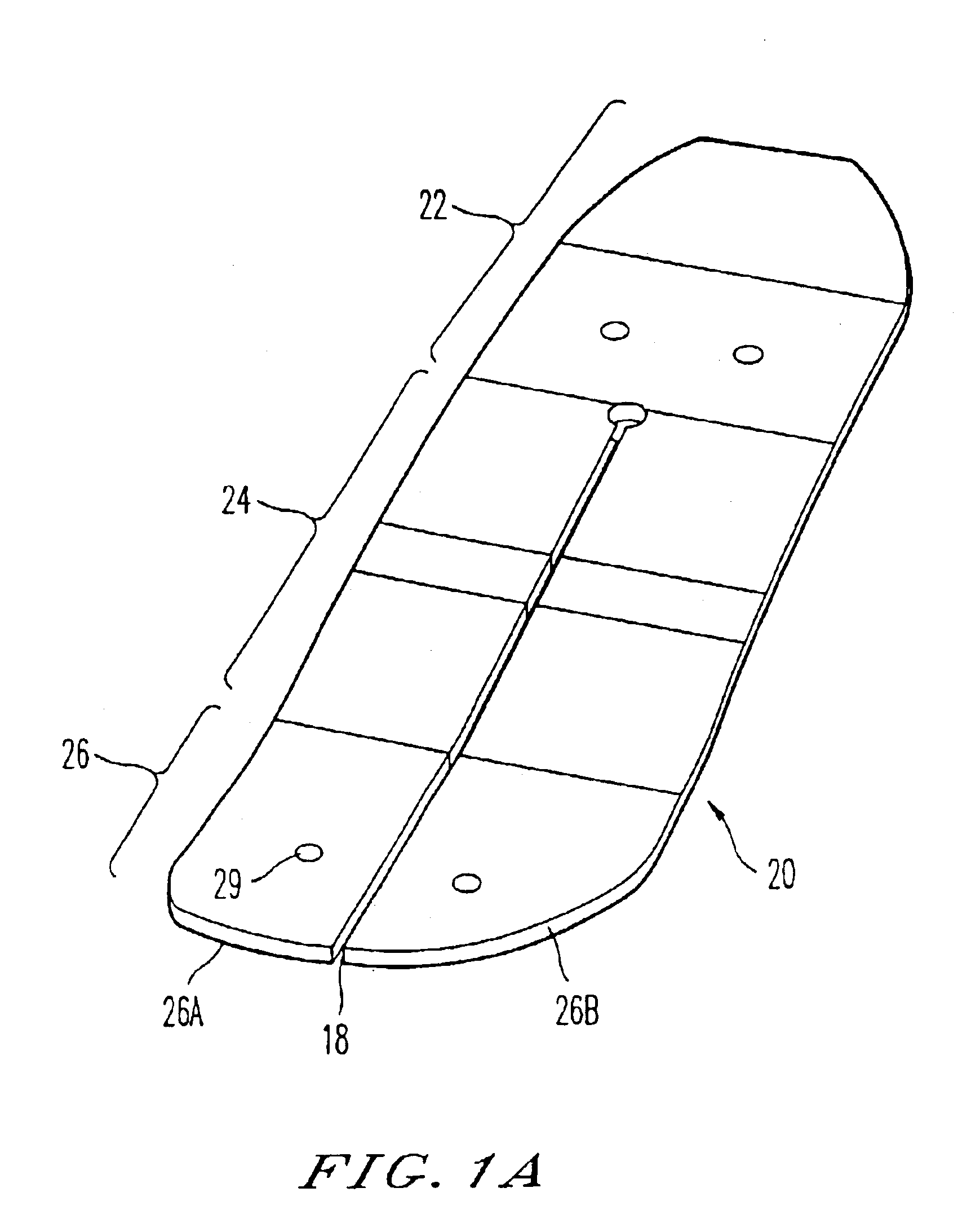
The contoured foot plate 20 is generally conventional and could be that disclosed in U.S. Pat. No. 4,865,612, except as set forth below. It includes a heel portion 22, an arch portion 24 and a ball portion 26 (FIG. 1a). A slot 28 may extend through the foot plate and longitudinally from the toe portion to the heel portion for all or part of the length of the foot plate, and thereby divide the toe portion into separate left and right toe parts 26A and 26B.

The foot plate is formed of a composite material which may be continuous carbon fibers in an epoxy matrix. It has r...

second embodiment

According to this embodiment, the top adapter 330 incorporates a collar 360 similar to that of the second embodiment, and which slides along a pylon 370. A heel spring 380 may be S-shaped and correspond to the further heel spring of the previous embodiment. As in the previous embodiment, a non-extensible band (not shown) limits the upward movement of the collar 360.


PUM


Abstract

A prosthetic foot includes an adapter element securable to a residual limb, a foot plate having a heel portion and a toe portion along the length thereof, at least one toe spring connected between the adapter element and the toe portion of the foot plate, and a heel spring connected between the adapter element and the heel portion. The heel spring may be a leaf spring or a tube type shock absorber. The concave side of the leaf spring exhibits a plurality of transverse ribs. Alternatively, a tubular pylon may have a collar mounted thereon for movement along the length of the pylon. A toe spring and a heel spring extend from the collar to form toe and heel portions of the prosthetic foot. A further heel spring is connected between the heel portion and another end of the pylon, and a non-extensible band extends between the heel portion and the collar. As another alternative, a tubular pylon has one end securable to a residual limb, and a collar is mounted to the pylon for movement along the length of the pylon. At least one toe spring is connected between the collar and the toe portion of a foot plate, while a heel spring is connected between the heel portion of the foot plate and another end of the pylon.

Description

BACKGROUND OF THE INVENTION1. Field of the InventionThe invention is directed to a prosthetic foot which is able to absorb the shocks developed during ambulation with efficient energy transfer between heel strike and toe-off, and to enhance stability.2. Description of the Related ArtSpecialized prosthetic feet have recently been developed in an effort to satisfy the specialized needs of different amputees. For example, active amputees who engage in sports or other strenuous physical activities typically require a prosthetic foot which is capable of both absorbing energy during a heel strike of each step, of efficiently transferring the energy to the toe of the prosthesis as the step progresses, and of releasing the stored energy at the moment of toe-off to provide energy for the next step.In particular, during ambulation the foot initially contacts the ground at the heel. During strenuous activities, it is desirable for a prosthesis to be able to absorb the shock of this heel strike...

Claims


Application Information

Patent Timeline
Patent Type & Authority Patents(United States)
IPC IPC(8): A61F2/66A61F2/60A61F2/50
CPCA61F2/66A61F2002/5003A61F2002/6657A61F2002/5079A61F2002/5072
Inventor DODDROE, JEFFREY L.ARBOGAST, ROBERT E.COLVIN, JAMES M.CAPPER, JAMES W.SRINIVASAN, SUJATHA
Owner THE OHIO WILLOW WOOD CO INC
Why Eureka
Try Eureka