
Self centering spin nock

a spin nock and self-centering technology, applied in the direction of arrows, etc., can solve the problems of reducing the kinetic energy available for forward motion of the arrow, reducing the friction coefficient of the arrow, and struggling with the problem of promotion, so as to achieve low friction coefficient, reduce resistance, and transfer energy efficiently

Inactive Publication Date: 2015-12-15
HARDING MARTIN DALE
View PDF7 Cites 9 Cited by
  • Summary
  • Abstract
  • Description
  • Claims
  • Application Information

AI Technical Summary

Benefits of technology

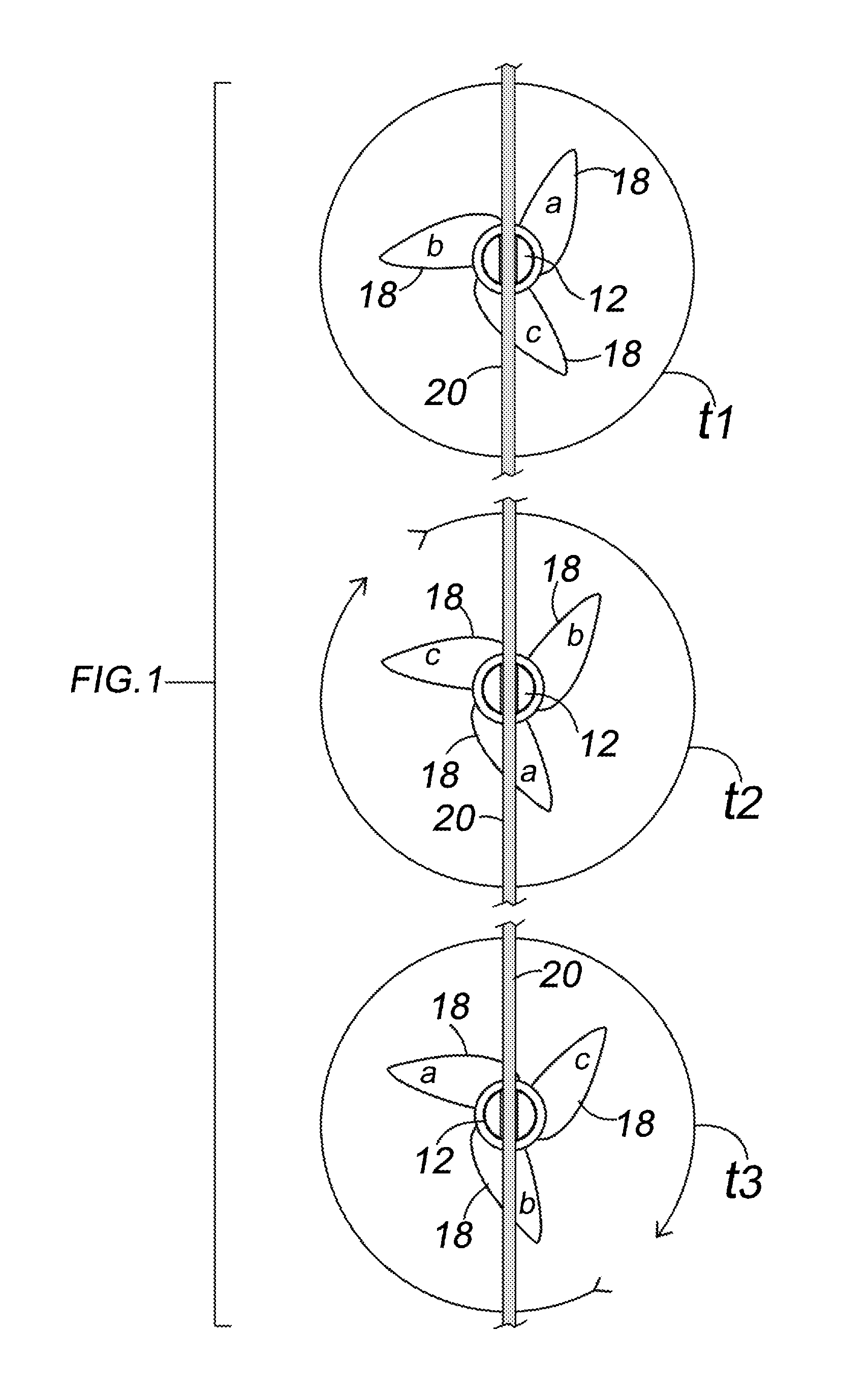
The invention allows for a smooth and efficient transfer of energy from the bowstring to the arrow shaft using a low-friction injection molded parts and tolerances made possible by sonic welding assembly. The parts rotate with very little resistance, allowing the shaft to start rotating before separation from the bowstring. This results in a rotational force on the shaft that is consistent with air resistance and vane configuration, promoting arrow stabilization with minimized drag and without any bowstring torque.

Problems solved by technology

Thus, a conventional nock (1) robs the arrow of energy by immobilizing the arrow shaft and preventing fletching rotation when moving through the air, which produces drag on the arrow during the initial release phase, and (2) interferes with early stabilization that would occur at the onset of release if the arrow were somehow permitted to begin spinning during the initial release phase.
Various devices in the past have struggled with the problem of promoting arrow spin; typically once the nock separates from the bowstring.
However, many such devices have included springs or spiraled guides that interfere with the natural tendencies of helical fletching to rotate the arrow shaft to assume a natural rotational equilibrium consistent with fletching geometry and other physical factors present at release, i.e., mass of the arrow, density of air, and the thrust imparted by the bow.
Accordingly, induced rotation exceeding natural rotation robs energy from the bow which reduces kinetic energy available for forward motion of the arrow.
Still another problem with devices that artificially increase rotation is the straining of the bowstring rest portion of the nock torquing against the bowstring when thrust forward by the released bowstring.
The correction to artificially induced rotational speed can be sudden.
In the case of a mass encountering a resistive fluid at a velocity beyond which the fluid can efficiently accomodate, much turbulence is produced as molecules of the fluid collide with each another and the moving mass.

Method used


Image

  • Self centering spin nock
  • Self centering spin nock
  • Self centering spin nock

Examples


Embodiment Construction

Reference Listing

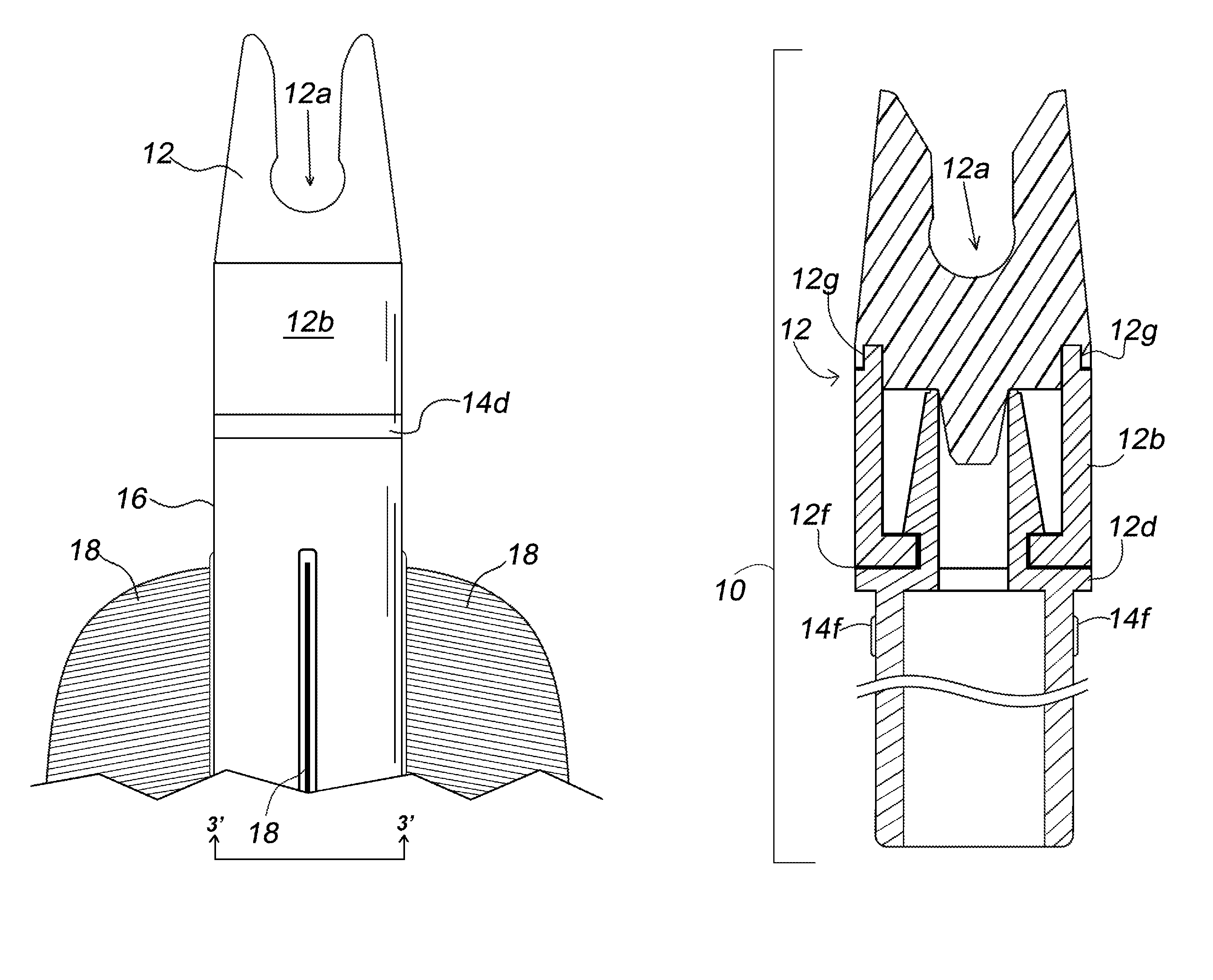
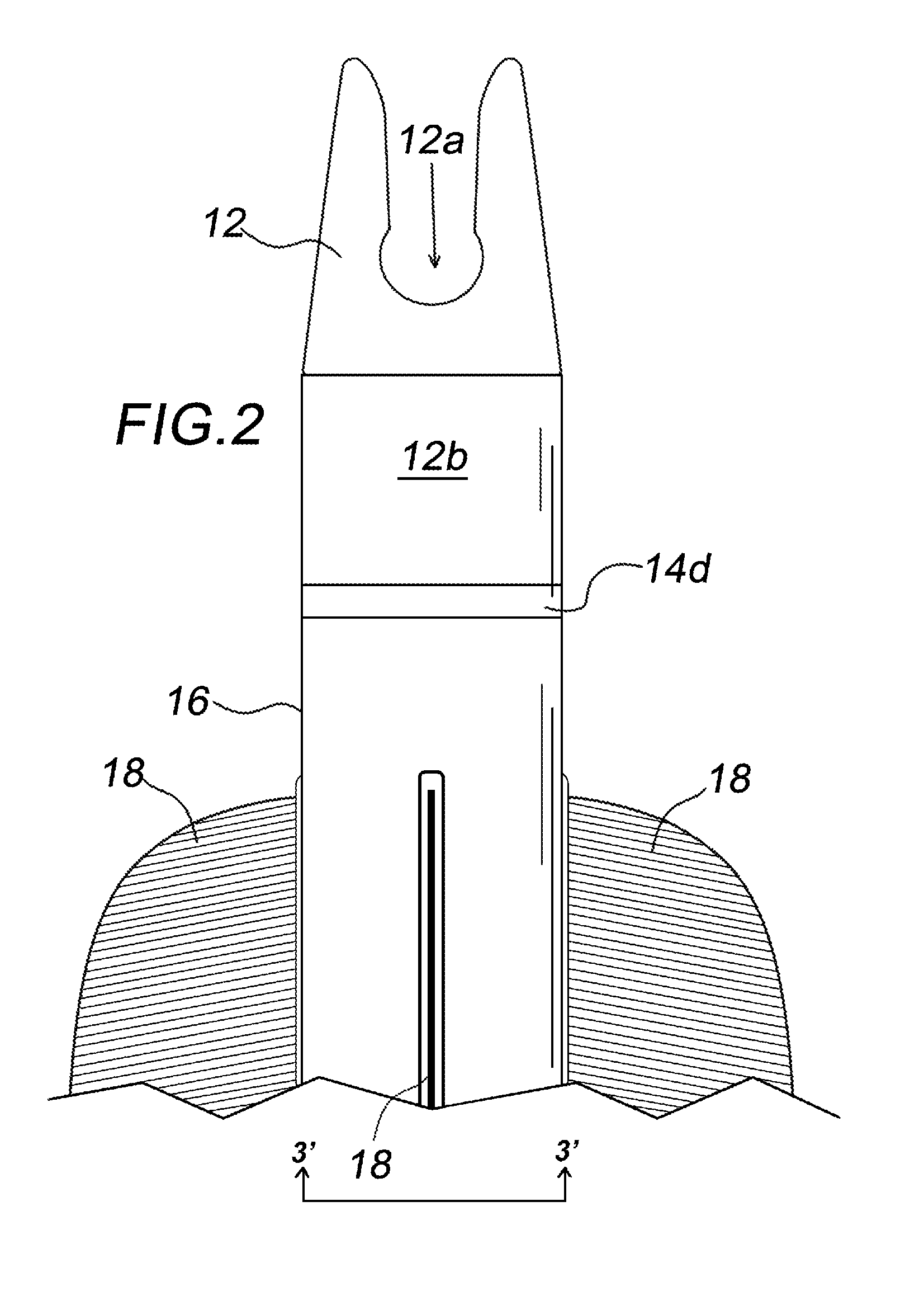
[0027]10′ nock assembly[0028]12 nock portion[0029]12a bowstring rest portion[0030]12b collar[0031]12c upper collar annulus[0032]12d lower collar annulus[0033]12e bowstring rest portion bottom[0034]12f interlocking members[0035]12g joint[0036]12h race[0037]12i lip[0038]14 retainer assembly[0039]14a projection[0040]14b shaft coupler[0041]14c thrust bearing[0042]14d plate[0043]14f friction fit tabs[0044]16 arrow shaft[0045]18 fletching[0046]20 bowstring

DEFINITIONS

[0047]The term “run-out” is a measure of the amount of off-centeredness of a rotating component. Unless otherwise explained, any technical terms used herein have the same meaning as commonly understood by one of ordinary skill in the art to which this disclosure belongs. The singular terms “a”, “an”, and “the” include plural referents unless the context clearly indicates otherwise. Similarly, the word “or” is intended to include “and” unless the context clearly indicates otherwise. Although methods and materia...


PUM


Abstract

A nock for promoting a natural spin on an arrow shaft prior to the nock separating from a bowstring includes a nock segment possessing a bowstring rest portion, and a base portion which is coupled to a retaining portion via a collar portion. The retainer is attached to the end of an arrow shaft. The nock segment freewheels independently of the retainer and the arrow shaft to permit the arrow fletching moving through the air to act on the shaft inducing a natural spin to the shaft prior to separation of the bowstring and the nock.

Description

FIELD[0001]The invention relates generally to the practice of archery, bowhunting, and more particularly, arrow nock construction.BACKGROUND OF THE INVENTION[0002]An archer's bow is a simple machine in which the limbs define a two-arm spring. An arrow consists of a forward tip which may be a target point type or a broadhead type affixed to one end of a shaft which is typically made from wood, fiberglass, metal or other suitable material, a nock for resting against a bowstring, and fletching, also known as fins or vanes, which are affixed to the shaft just ahead of the nock for purposes of aerodynamic stabilization during flight. The archer stores energy in the form of the drawn stressed bow. When the archer releases the bowstring permitting the bow limbs to spring forward kinetic energy is then transferred to the arrow. Among several factors affecting the distance an arrow flies are the initial angle, initial velocity, arrow weight, length of the arrow, and the size and shape of the...

Claims


Application Information

Patent Timeline
Patent Type & Authority Patents(United States)
IPC IPC(8): F42B6/06
CPCF42B6/06
Inventor HARDING, MARTIN DALE
Owner HARDING MARTIN DALE
Learn More