
Inductively generated streaming plasma ion source

Active Publication Date: 2005-04-28
EXCELITAS TECH
View PDF12 Cites 31 Cited by
  • Summary
  • Abstract
  • Description
  • Claims
  • Application Information

AI Technical Summary

Benefits of technology

[0016] The present invention provides a pre-ionization method which decreases the required electric field for prompt ionization of the neutral gas thereby increasing the efficiency of the ion source. This pre-ionization method includes a pre-ionization coil which is inductively coupled to the set of coils. The pre-ionization coil possesses a gap, for generating seed electrons, coupled in series with a high impedance circuit element, for limiting the current through the gap.
[0019] The present invention provides a tank circuit for efficiently transferring the energy from the power supply to the set of coils. The tank circuit includes the set of coils in parallel with a capacitance.

Problems solved by technology

For many high current applications, sources which use electrodes may not be suitable, because electrodes have a limited lifetime, may require cooling, and introduce impurities into the plasma.
On the other hand, a hot filament requires a separate power supply and also has a limited lifetime.
This type of fast valve opens and closes faster than the electromagnetic valves, but some of them have problems which reduce the quality and lifetime of the valve.
However, due to material property differences, clamping forces, adhesion forces, and other factors, one could not be assured of a uniform gas density around the annular puff.
Also, deflection of the metal disk results in metal fatigue, which can limit the lifetime of the disk.

Method used


Image

  • Inductively generated streaming plasma ion source
  • Inductively generated streaming plasma ion source
  • Inductively generated streaming plasma ion source

Examples


Embodiment Construction

[0035] This section includes the descriptions of the present invention including the preferred embodiment of the present invention for the understanding of the same. It is noted that the embodiments are merely describing the invention. The claims section of the present invention defines the boundaries of the property right conferred by law.

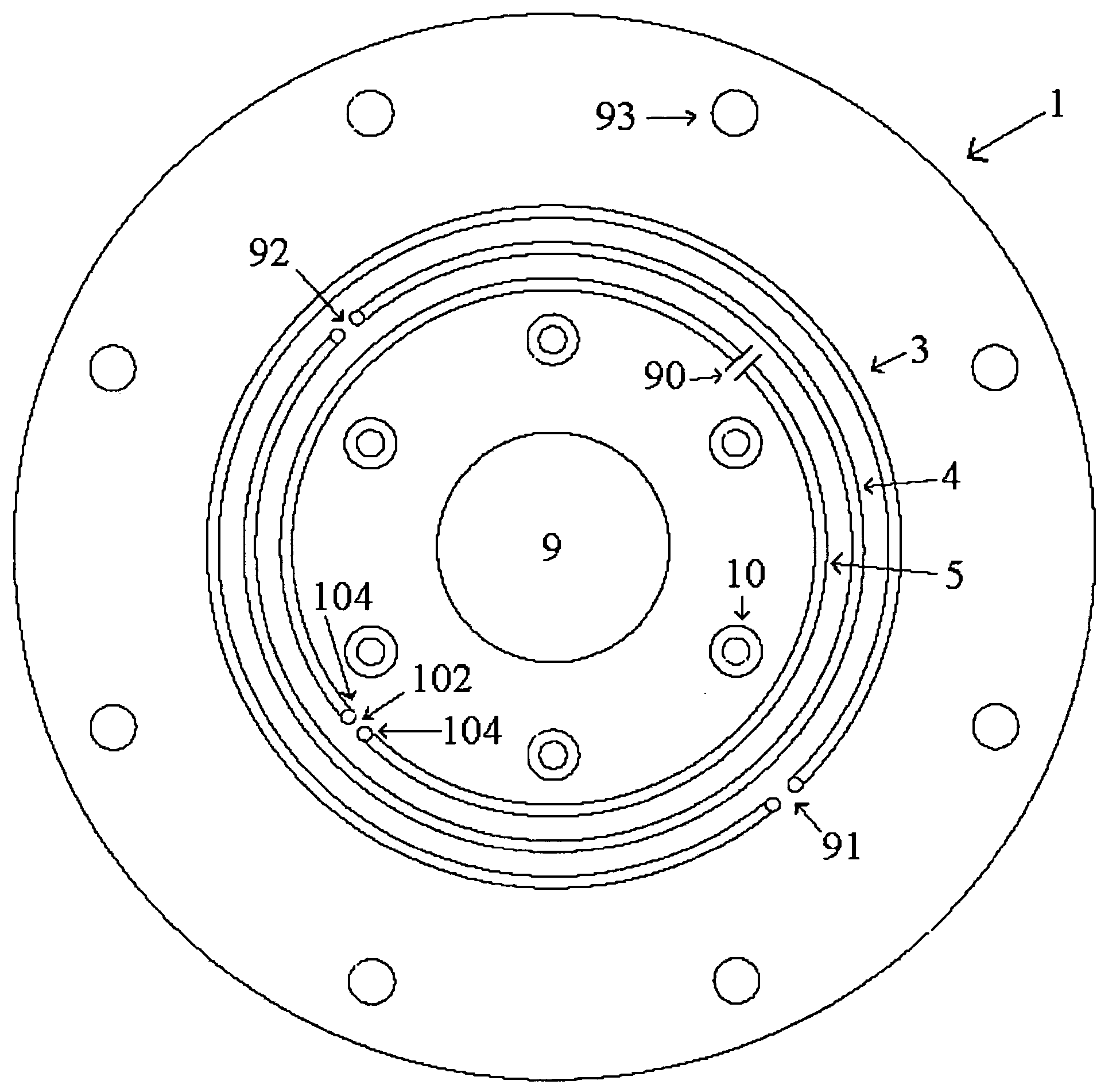
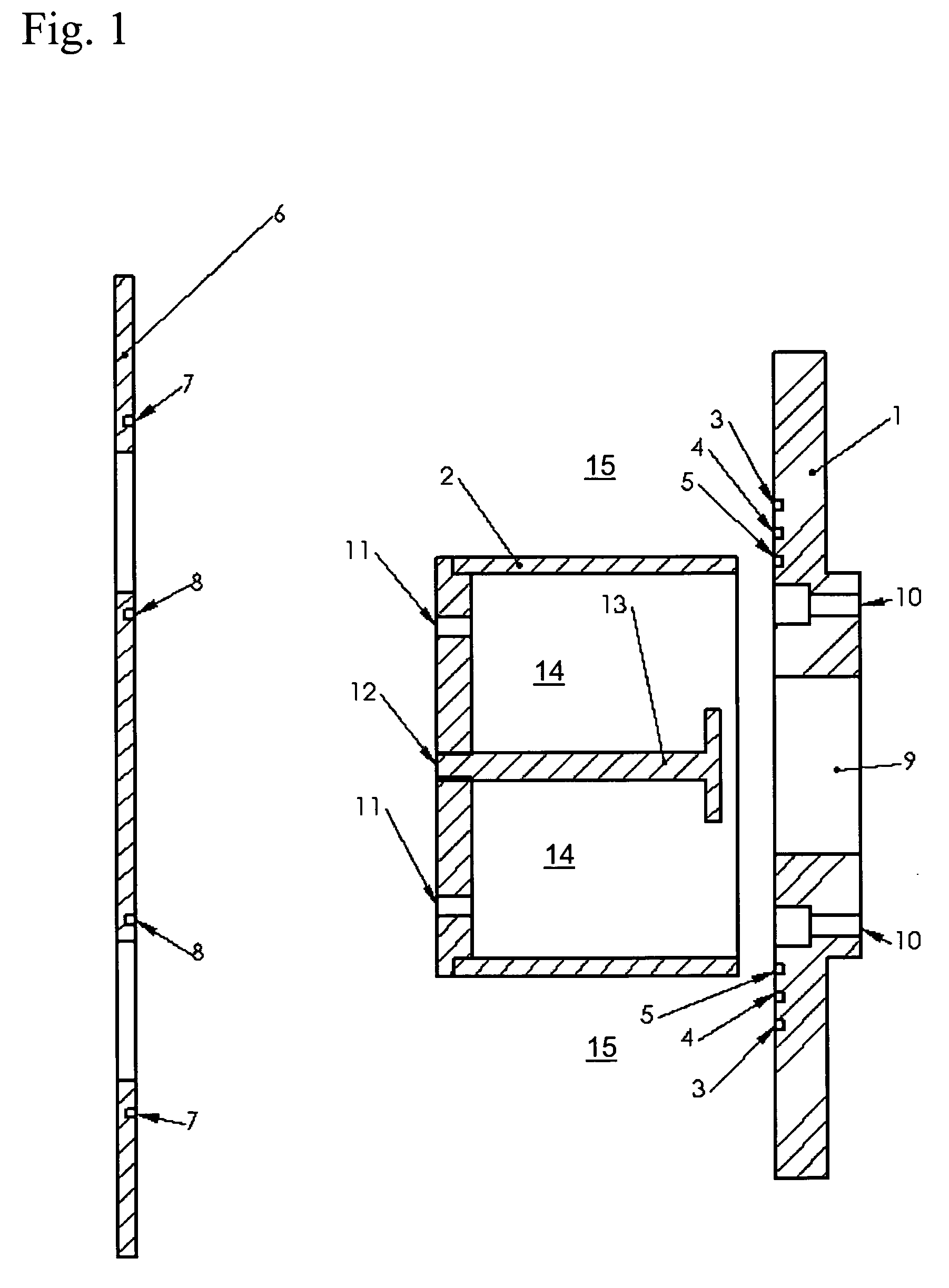
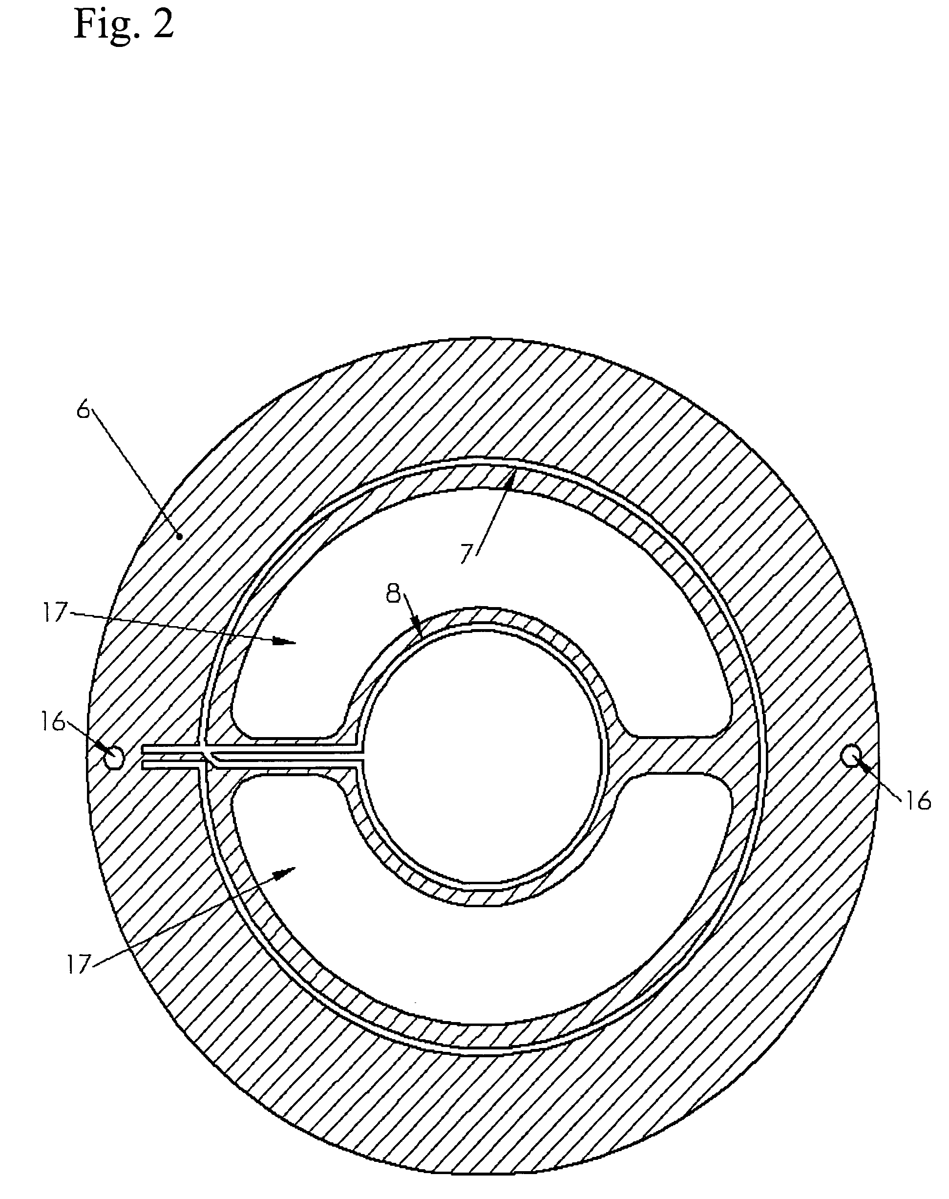
[0036] Referring to FIGS. 1-8, specifically referring now to FIG. 1 wherein the basic structure of the inductively generated streaming plasma ion source of the present invention is depicted. The source comprises a backplane 1, a nozzle 2, and a modulator 6. The backplane 1 includes a set of coils 3, 4, 5, mounting holes 10, and a place or region to insert a gas supply 9. The nozzle 2 is shaped like a cup with a set of mounting holes 11, 12 or outer mounting holes 11 and central mounting holes 12 on the bottom or a first side of nozzle 2. The outer mounting holes 11 are used to mount the nozzle 2 onto a member. The central mounting hole 12 is used...


PUM

PropertyMeasurementUnit
Magnetic fieldaaaaaaaaaa
Electrical inductanceaaaaaaaaaa
Currentaaaaaaaaaa

Abstract

A novel pulsed, neutralized ion beam source is provided. The source uses pulsed inductive breakdown of neutral gas, and magnetic acceleration and control of the resulting plasma, to form a beam. The beam supplies ions for applications requiring excellent control of ion species, low remittance, high current density, and spatial uniformity.

Description

REFERENCE TO PROVISIONAL APPLICATION [0001] This application claims an invention which was disclosed in Provisional Application No. 60 / 515,050, filed Oct. 28, 2003, entitled “INDUCTIVELY GENERATED STREAMING PLASMA ION SOURCE”. The benefit under 35 USC §119(e) of the U.S. provisional application is hereby claimed, and the aforementioned application is hereby incorporated herein by reference.ACKNOWLEDGMENT OF GOVERNMENT SUPPORT [0002] This invention was made with Government support under Grant No. DE-FG02-01ER83147, awarded by the Department of Energy. The government has certain rights in the invention.FIELD OF THE INVENTION [0003] The invention pertains to the field of ion beam sources. More particularly, the invention pertains to sources for pulsed neutralized ion beams which are used in areas such as material modifications, fusion energy research, and space propulsion. BACKGROUND OF THE INVENTION [0004] A neutralized ion beam is a stream of ions with directed velocity, accompanied ...

Claims


Application Information

Patent Timeline
IPC IPC(8): H01J7/24H01J27/02
CPCH01J27/02
Inventor GLIDDEN, STEVEN C.SANDERS, HOWARD D.GREENLY, JOHN B.
Owner EXCELITAS TECH
Learn More