Device for transferring light signals between two elements relatively movable to one another

a technology of light signals and moving parts, applied in the direction of photometry using electric radiation detectors, optical radiation measurement, instruments, etc., can solve the problems of increasing the power requirement and limited number of light sources which can be used for data transfer, and achieve reliable data transfer, reduce power consumption, and energy-efficient light signal transfer

Inactive Publication Date: 2011-09-27
SIEMENS AG
View PDF15 Cites 0 Cited by
  • Summary
  • Abstract
  • Description
  • Claims
  • Application Information

AI Technical Summary

Benefits of technology

[0012]In other words, an important concept of the present invention consists in configuring the device in such a manner that it has a unit by means of which the light sources can be activated or deactivated in targeted group fashion. A reduction in the power consumption and an energy-efficient transfer of light signals between the elements are thus achieved in an advantageous manner by the device according to the invention.
[0013]By preference, the unit is configured in such a manner as to perform the selection of the portion of the light sources turned on / off on the basis of a received signal, whereby in one embodiment the signal reproduces a position of the first element adopted as a result of the relative movement with respect to the second element. As a result of the targeted activation or deactivation of only one portion of the light sources depending on the position of the two elements relative to one another, a reliable transfer of data by means of light signals is also achieved in addition to the reduction in power consumption. For this purpose, in particular only those light sources can be activated which are directed at the photoreceiver at a particular point in time. Moreover, it is possible to increase the intensity of the luminous flux of the currently activated portion of the light sources in such a manner that a correspondingly lower sensitivity is required for the photoreceiver arranged on the second of the two elements. By this means, the signal-to-noise ratio of the light signals, in other words the ratio of the useful signal to an electrical or optical noise signal, can be significantly increased. Furthermore, the sensitivity of the device to the electromagnetic fields occurring in the machine and the EMC interference effects are thus reduced.
[0014]In one embodiment, a facility for determining a relative position of the first element with respect to the second element can be provided, by means of which the signal can be generated. The reliability of the data transfer is further increased through this facility, which is capable of determining the current position of the two elements relative to one another and generating a signal reproducing this position.
[0015]By preference, the facility has a further single light source arranged on the second element and also a group of photoreceivers arranged on the first element for determining the relative position. In particular, the number of photoreceivers of the facility for determining the relative position is essentially the same as the number of light sources for delivery of the light signals. By this means, a resolution of the facility suitable for determination of the relative position can be achieved. In particular, the further single light source can be arranged on front face of the second element facing the first element, whereby the photoreceivers can preferably be arranged on a front face of the first element facing the second element. Moreover, it is possible to arrange the photoreceivers evenly spaced from one another.
[0019]In an alternative embodiment, the light signals can be transferable in the radial direction. In this situation, it proves advantageous if the two elements are arranged concentrically. This serves to ensure that the axial overall length of the two elements can be significantly minimized, as a result of which a device is created which offers reduced costs in respect of production and also saves on space.
[0021]In one embodiment, the second element has a further group of light sources for emitting light signals and the first element has at least one further photoreceiver for receiving the light signals. Through simple duplication of the components it is thus possible in an advantageous manner to create a bidirectional data transfer device.

Problems solved by technology

One disadvantage of this implementation consists in the fact that the power requirement is considerably increased as a result of the plurality of light sources.
Thus, in the case of this known transfer system, a separate connection is required for a voltage or power supply because the power supplies introduced in the standard bus lines or introduced with regard to special bus systems do not suffice.
On the other hand, the necessary number of light sources which can be used for the data transfer is limited by the amount of power available.

Method used


Image

  • Device for transferring light signals between two elements relatively movable to one another
  • Device for transferring light signals between two elements relatively movable to one another

Examples


Embodiment Construction

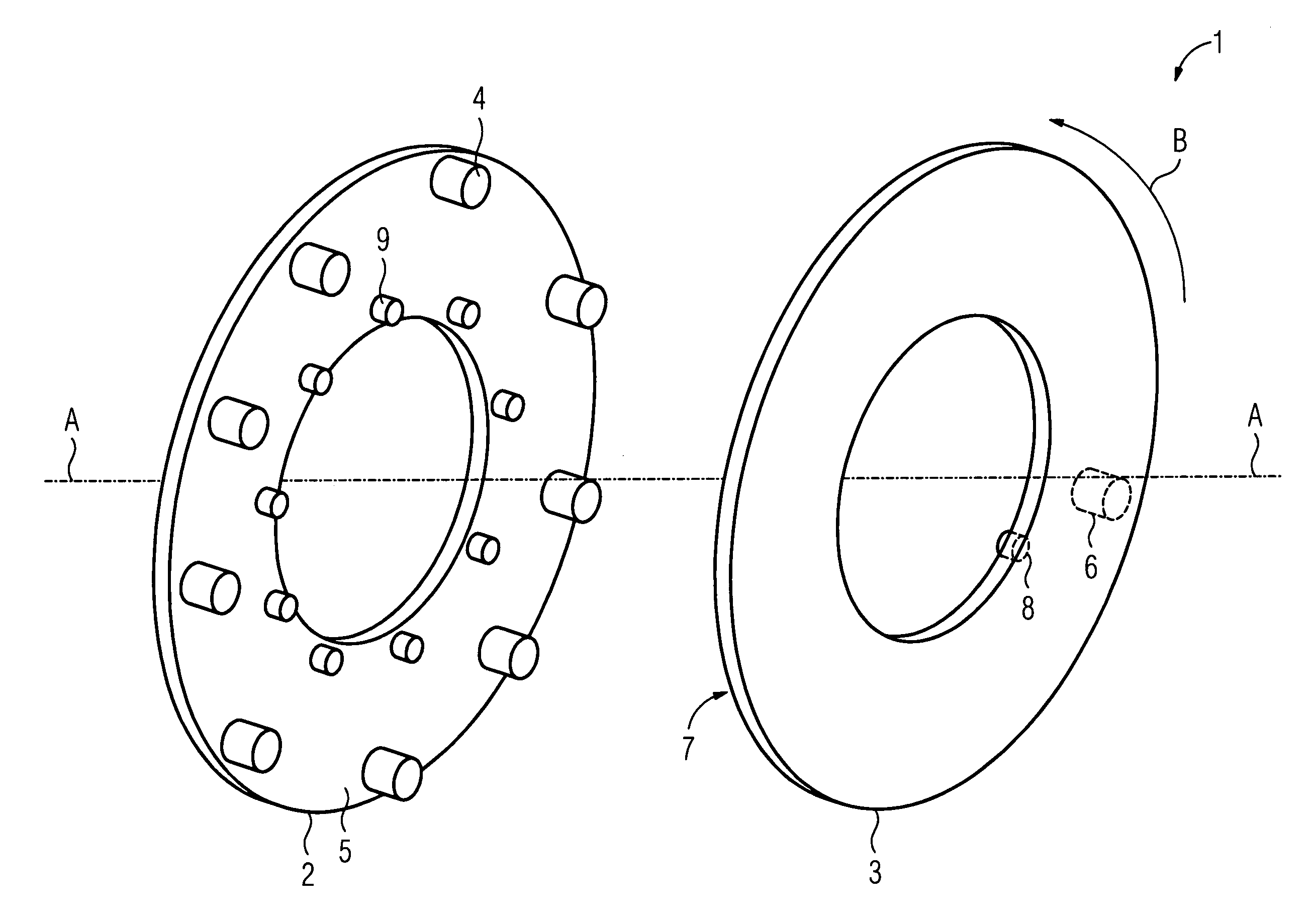
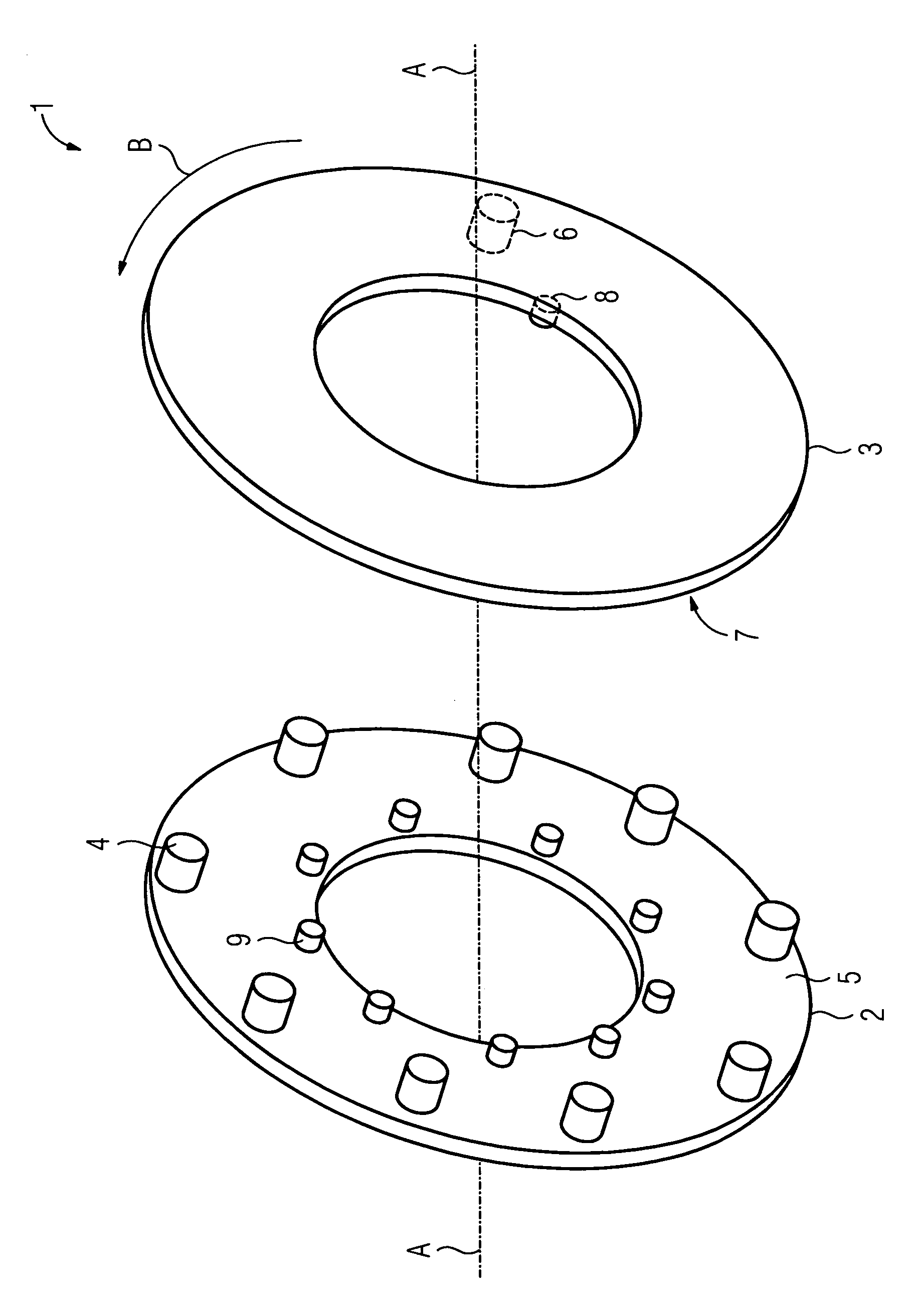
[0027]A device 1 illustrated in the FIGURE comprises two elements 2, 3 of a machine tool which are capable of rotary movement relative to one another, between which light signals are transferred. In the present case, the first element 2 is designed as a fixed printed circuit board and coupled to a control cabinet of the machine tool. On the other hand, the second element 3 is a printed circuit board mounted to be capable of rotary movement, which in the present example represents a part of a hollow shaft of the machine tool. The two printed circuit boards 2, 3 are designed as ring-shaped and are arranged axially with respect to one another in such a manner that the printed circuit board 3 mounted to be capable of rotary movement can rotate around an axis of rotation A in a direction illustrated in the FIGURE by means of an arrow B.

[0028]In order to ensure wireless communication between the two printed circuit boards 2, 3, the fixed printed circuit board 2 has a group of light source...


PUM


Abstract

To ensure an energy-efficient transfer of light signals between two elements of a machine which are movable relative to one another, a device and a method for transferring light signals between such elements is provided. A first element has a plurality of light sources for delivering light signals and a second element has at least one photoreceiver for receiving the light signals. A unit causing the turning on or off is configured such as to effect a turning on or off of only one portion of the light sources.

Description

CROSS REFERENCE TO RELATED APPLICATIONS[0001]This application claims priority of European Patent Office application No. 07024426.4 EP filed Dec. 17, 2007, which is incorporated by reference herein in its entirety.FIELD OF INVENTION[0002]The present invention relates to a device for transferring light signals between two elements of a machine which are movable relative to one another, in particular of a machine tool, on which a first of the elements has a group of light sources for delivering such light signals and a second of the elements has at least one photoreceiver for receiving the light signals. Moreover, the invention relates to a corresponding method.[0003]Of interest in the present case is a transfer of information, in particular of field bus signals, between machine elements which move relative to one another. The relative movement in this situation is understood in particular to be a rotary movement. The concept however also includes other types of movement, such as a lin...

Claims


Application Information

Patent Timeline
Patent Type & Authority Patents(United States)
IPC IPC(8): G01D5/34G01J5/08G02B27/00H04B10/00
CPCH04B10/22H04B10/801
Inventor HEMMETER, GEORGSCHWESIG, GUNTER
Owner SIEMENS AG
Why Eureka
Try Eureka