Distributed control system for powder coating system

a control system and powder coating technology, applied in the direction of programme control, total factory control, electric programme control, etc., can solve the problems of complex data structure, complex arithmetic operations, and inability to perform complex arithmetic operations, etc., to achieve more uniform powder coating, save system downtime and operator time, and high flexibility

Inactive Publication Date: 2005-03-08
NORDSON CORP
View PDF27 Cites 27 Cited by
  • Summary
  • Abstract
  • Description
  • Claims
  • Application Information

AI Technical Summary

Benefits of technology

pensing cycles. Therefore, another advantage of the invention is that, for the first time, a powder dispensing process can be programmed that changes powder spray parameters in real time.
In a still further embodiment, the invention includes a method of operating a powder coating system in which the plurality of gun controls are automatically initialized and brought on-line in a fully operable state without any operator intervention. The control system has the capability of detecting when one gun control is replaced by another, or when a new gun control is added to the system. Consequently, the met

Problems solved by technology

This centralized system control configuration has a disadvantage of requiring extensive wiring within the painting facility much of which must be done upon installation at the user's site.
Moreover, a PLC is not adept at performing complex arithmetic operations and handling more complex data structures.
PLC's have the further disadvantage of only providing a limited amount of process status information to the operator or other analytical devices.
Furthermore, the use of a PLC as the centralized control system has a further disadvantage in that it is difficult and expensive to change the electrical configuratio

Method used


Image

  • Distributed control system for powder coating system
  • Distributed control system for powder coating system
  • Distributed control system for powder coating system

Examples


Embodiment Construction

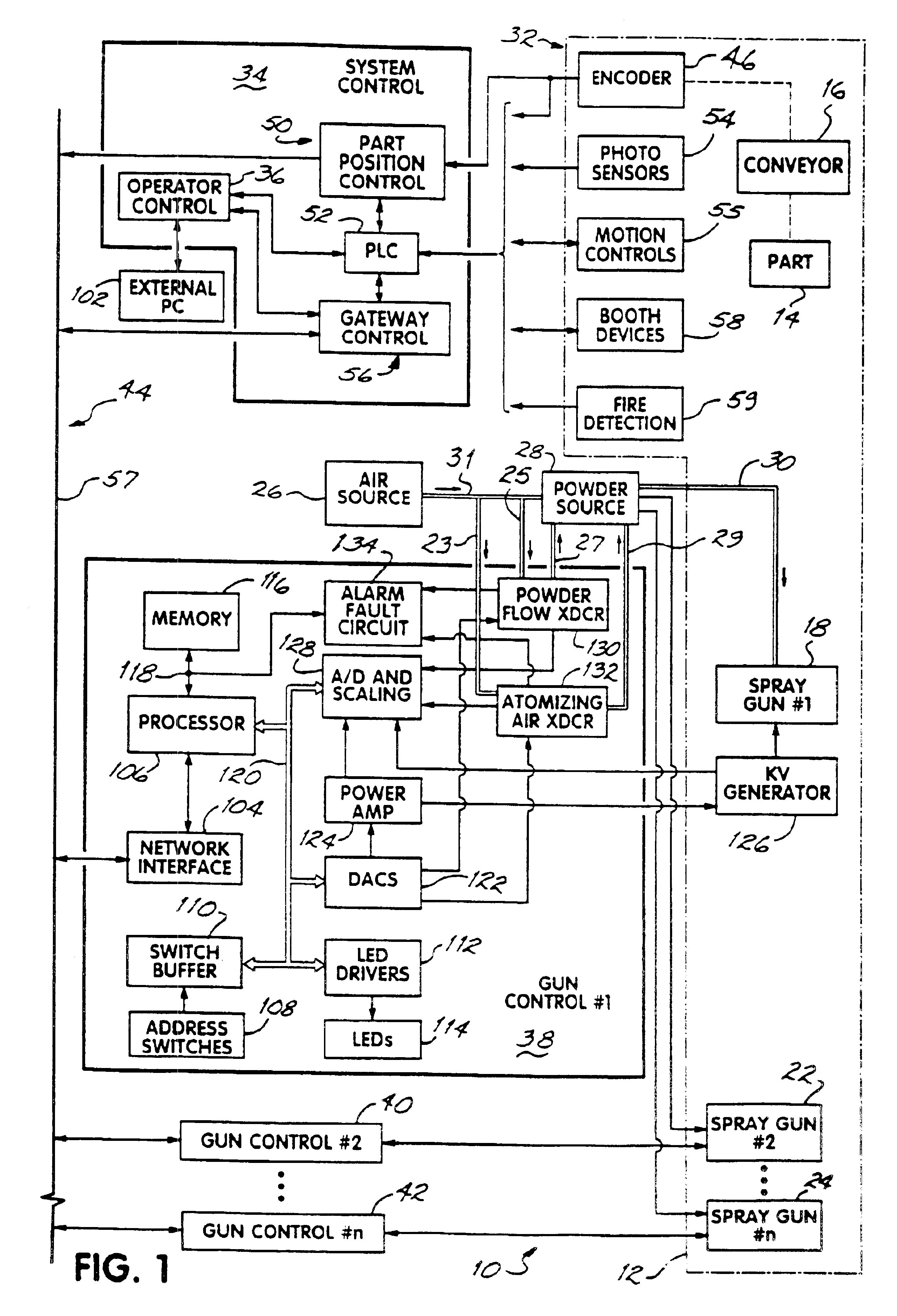
FIG. 1 illustrates a preferred embodiment of the powder coating system 10 of the present invention. The system 10 includes a powder spray booth 12 shown in phantom in which an article or part 14 to be coated is mechanically supported on a conveyor 16. A powder coating is electrostatically deposited on the part 14 and is subsequently heated to cause the powder coating to flow together and harden on surfaces of the part. The powder is sprayed on to the part from an electrostatic powder spray gun 18. Other powder spray guns 22,24 are also located in the powder spray booth 12 at different locations to spray, either at the same or different elevations, different portions of the same part, or, different parts at the same or different elevations, or, different surfaces, etc.

In a well known manner as is described in the Gimben, et al. U.S. Pat. No. 5,167,714, assigned to the assignee of the present invention, pressurized air, such as “shop air” is dried and distributed to an air distributio...


PUM

PropertyMeasurementUnit
Flow rateaaaaaaaaaa
Electric potential / voltageaaaaaaaaaa

Abstract

A powder coating control system comprising a plurality of gun controls associated with a like plurality of powder spray guns. Each of the gun controls stores a plurality of presets spray parameters. Each of the gun controls responds to part identification signals and part position signals to select in real time one of the stored presets of spray parameters and trigger its respective powder spray gun ON and OFF to apply a powder coating to the moving part in accordance with the selected set of spray parameters. The control system further permits a gun purge cycle to be programmed either before or after the powder coating process is executed. The control system automatically initializes and brings each of the gun controls to an operable state on-line with the system control.

Description

FIELD OF THE INVENTIONThe present invention relates generally to a powder coating system and more particularly to a distributed control system providing a gun control for each spray gun which selects a particular one of a plurality of stored sets of powder dispensing parameters and independently controls the triggering of its powder spray gun.BACKGROUND OF THE INVENTIONA powder coating system sprays an electrostatically charged airborne powder within an enclosure or booth containing the part or article to be coated. The electrostatic potential between the powder and the article causes the powder to be attracted to and move into contact with the surface of the article. The deposited powder is then heated so that it flows and hardens on the surface on which it has been deposited.The present invention relates to two areas of powder spray control. First is the selection and control of certain spray parameters, for example, the powder flow air pressure, the atomizing air pressure and pat...

Claims


Application Information

Patent Timeline
IPC IPC(8): G05B19/418G05B19/414B05C19/04B05C19/06
CPCG05B19/4148G05B19/41815G05B19/41885B05B12/004B05B5/08G05B2219/45013G05B2219/31139G05B2219/31228G05B2219/32145G05B2219/33105G05B2219/33107G05B2219/33113G05B2219/33126G05B2219/33142G05B2219/33273G05B2219/34304G05B2219/34492G05B2219/35266G05B2219/36509B05B12/006B05B12/04B05B12/122B05B13/0264Y02P90/02B05B12/00B05C19/04
Inventor CRUM, GERALD W.DIXSON, JR., EDDIE W.GATIAN, III, CHARLES L.LEIDY, JEANNE MARIERUCKI, WILLIAM MARKSCHROEDER, JOSEPH G.SKELTON-BECKER, CYNTHIA
Owner NORDSON CORP
Why Eureka
Try Eureka