It is a feature of the present invention that components in the circuit for driving a
gas discharge lamp will not overheat and / or will not cause an over-
voltage at the lamp terminals in starting with intermittent operation. The lamp will start and re-start reliably after a breakdown and will then transition into a normal operation by applying an equivalent
DC current through the lamp right after the breakdown or by providing ample time to cool the lamp before re-starting.
The intermittent operation has four periods. A first period comprises an ignition period that lasts t1 seconds. During this period, a very high resonant
ignition voltage appears at the lamp terminals. A second period follows the first period and lasts t2 seconds. During this period, the output is off. In the disclosed invention, the time period t2 is generally more than 10 times longer than t1. However, the period of time period t2 can vary without departing from the spirit and / or scope of the invention. A third period, t3, is a multiple of the combination of times t1 and t2. That is, times t1 and t2 are repeated for the duration of time t3. A fourth period follows the third period, with all switches being in an off mode. This period, generally, is on the order of minutes. The purpose of this period is to provide ample time for the lamp to cool before the next burst of
ignition voltage. This method avoids the situation of a lamp being stuck in a glow mode.
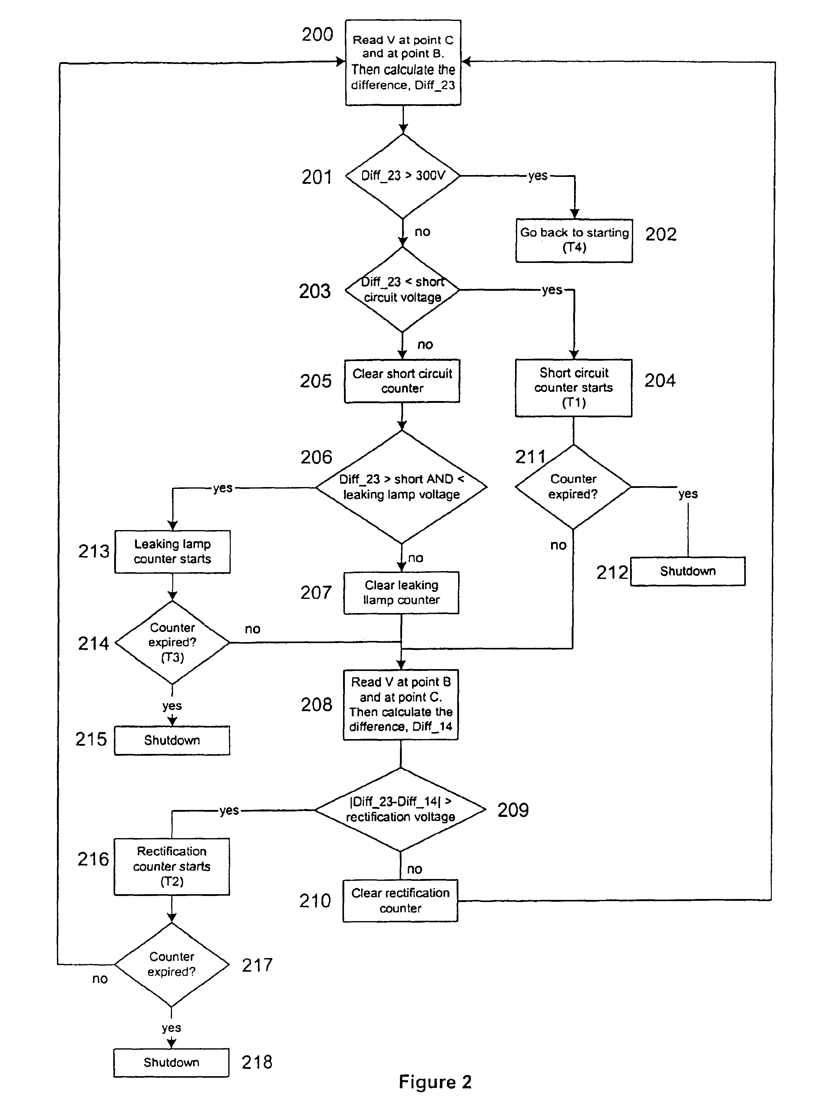
Another feature of the invention is that the circuit for driving a
gas discharge lamp can safely and reliably disengage the lamp with different
time delays depending upon what kind of faults occur at the lamp. The faults can be, for example, shorted lamp leads, rectified lamp electrodes, a leaking arc tube, and no lamp being present. However, it is understood that alternative faults may also be sensed by the present invention without departing from the spirit and / or scope of the present invention.
With respect to the one-pulse-mode (OPM) function, in the normal operation, one of the timers starts to count on a rising (or a falling) edge of a turn-on
signal. At least two variables are associated with the
timer. When the
timer count reaches a first variable before another new turn-on
signal, the
low frequency side switches (Q1& Q2) will be turned off. When the
timer count reaches a second variable, a turn-on
signal is generated. One of the
high frequency side switches (Q3 or Q4) is forced to turn on. The first variable will be reached only when the lamp
voltage is lower than a typical value. The second variable will be reached only when no turn-on signal is generated from the ZCS circuitry within the duration of the second variable. If desired, additional variables may be employed. The duration of the second variable corresponds to a minimum frequency at which the gas
discharge lamp
driving circuit will operate. Through the use of the timers, an audible
noise is avoided. It is noted that the at least two variables can be either fixed or adaptive to the lamp voltage.
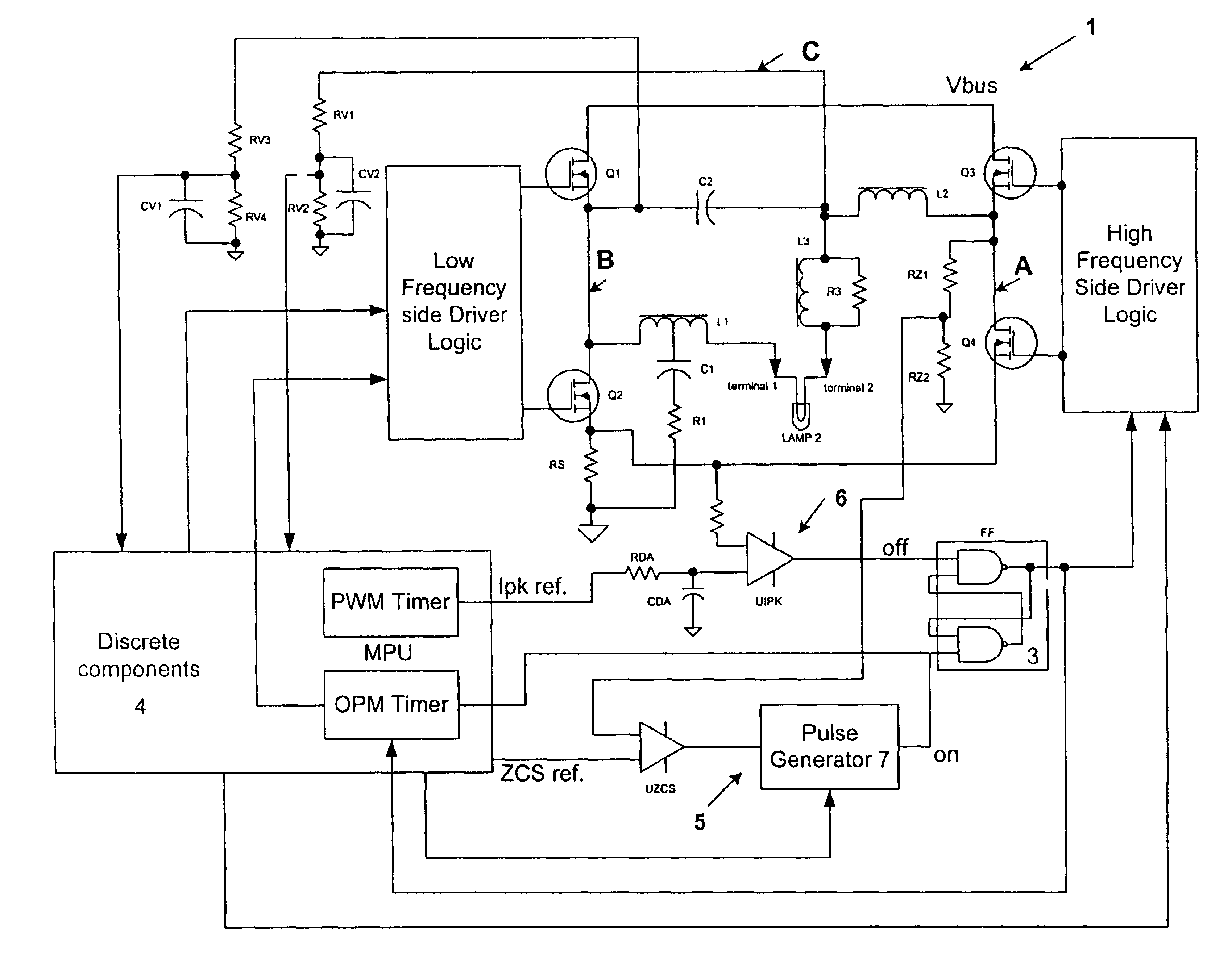
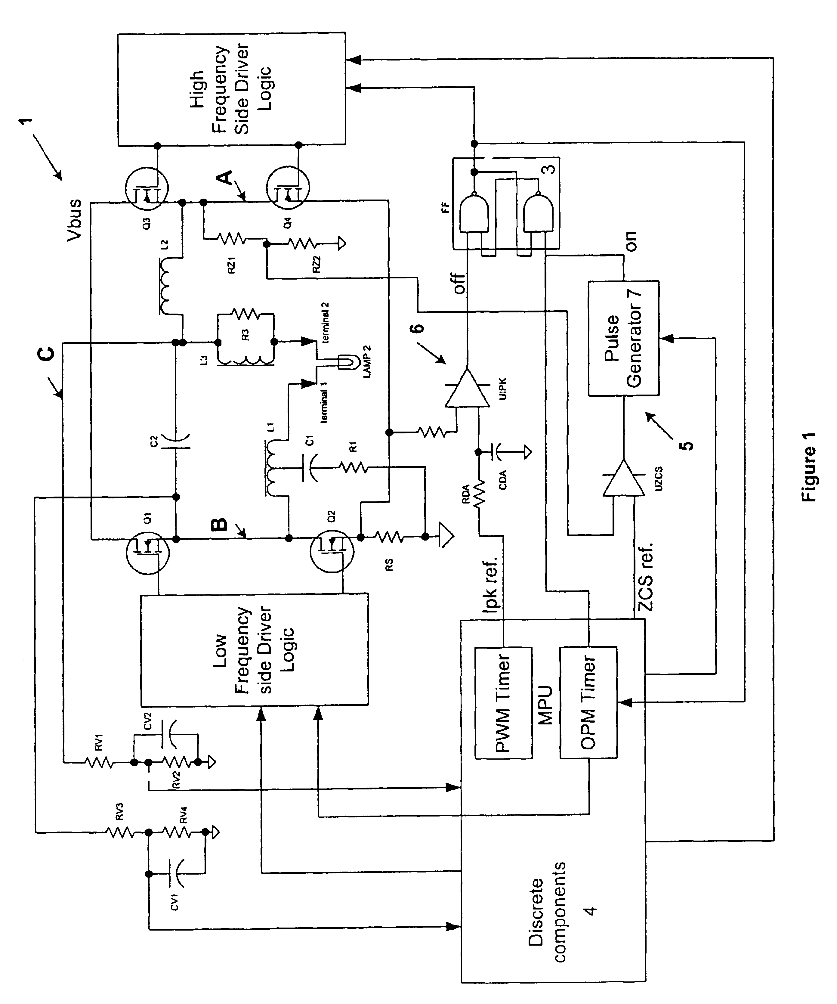
According to another feature of the present invention, a circuit that drives a gas
discharge lamp is powered from a
DC voltage source from either a rectified and / or filtered AC source or from a pre-conditioner such as boost
power factor correction (PFC) convertor. In the latter case, the voltage can be different between a starting operation and a normal operation. A higher
DC bus voltage may be better in the starting operation to generate the ignition voltage, while a lower
DC bus voltage in the normal operation helps to reduce power losses. The reference voltage for the
peak current detection
comparator is generated by a filtered PWM
square wave from the controller. A
time constant of the filter is longer than a PWM's.
According to another feature of the present invention, the output power of the circuit that drives a gas discharge lamp is substantially flat for a lamp voltage of from approximately 70V to about 140V, whereas conventional electronic ballasts on the market usually output power parabolically from about 85V to about 120V. When the lamp voltage is greater than approximately 140V, the lamp power is reduced to protect the circuit from over powering. When the lamp voltage is further increased to approximately 250V, the lamp power is maintained at a predetermined
power level, such as, but not limited to, approximately 30W. This corresponds to a minimum output power that is needed to avoid hanging in a glow mode during a lamp warm-up after ignition. Because of the controlled output characteristics of the circuit from 0V to 300V, an incandescent lamp operation is possible.

