
Radar apparatus for imaging and/or spectrometric analysis and methods of performing imaging and/or spectrometric analysis of a substance for dimensional measurement, identification and precision radar mapping

a technology of spectrometry and radar, applied in the field of radar equipment, can solve the problems of limited analytical capabilities, unwieldy devices, crude imaging,

Inactive Publication Date: 2005-03-08
STOVE GEORGE COLIN
View PDF46 Cites 50 Cited by
  • Summary
  • Abstract
  • Description
  • Claims
  • Application Information

AI Technical Summary

Benefits of technology

A blind spot of the order of 1 meter in close proximity (the near range) to the radar apparatus could generate an equivalent position shift in the radar map of features detected. Such near range blind spots can thus be highly undesirable. By accurately locating the position of the zero time point in the received signal radar, such blind spots can be mitigated or obviated.
The inventor believes that a key feature of the invention is the set up of resonant conditions in the transmitter / receiver apparatus. This is affected by the dimensions and / or the geometry of a transmitter cavity and a receiver cavity which substantially surround respective transmitting and receiving antennae. In particular, the relative proportions of the lengths and widths of the antenna element(s) to the lengths and widths of the surrounding cavities are important. Ideally the internal diameter of an antenna cavity, whose walls may form the cathode element of an antenna in certain embodiments, is an integer multiple of the diameter of the internal antenna anode element, and similarly, the internal length of the is ideally an integer multiple of the length of the antenna anode element. The resonant conditions may be further affected by at least partially cladding the antennae element(s) with a suitable dielectric cladding material. Furthermore, the selection of a suitable dielectric material to clad the transmitting and receiving antenna elements is believed to further assist in the near range focusing and in more accurately pin-pointing the zero time position, the start position for range measurements.

Problems solved by technology

Although ground penetrating radars (GPRs) are already known as non-destructive testing tools their analytical capabilities have been restricted and imaging is often crude using conventional devices.
Furthermore, they are often unwieldy devices and require skilled technical operators.
Accurate location of the zero time point is important and can be a difficult procedure: inaccurately pinpointing the zero time introduces a systematic shift in the location of all radar measurements.
Such near range blind spots can thus be highly undesirable.

Method used


Image

  • Radar apparatus for imaging and/or spectrometric analysis and methods of performing imaging and/or spectrometric analysis of a substance for dimensional measurement, identification and precision radar mapping
  • Radar apparatus for imaging and/or spectrometric analysis and methods of performing imaging and/or spectrometric analysis of a substance for dimensional measurement, identification and precision radar mapping
  • Radar apparatus for imaging and/or spectrometric analysis and methods of performing imaging and/or spectrometric analysis of a substance for dimensional measurement, identification and precision radar mapping

Examples


Embodiment Construction

Firstly, apparatus embodying various aspects of the invention will be described.

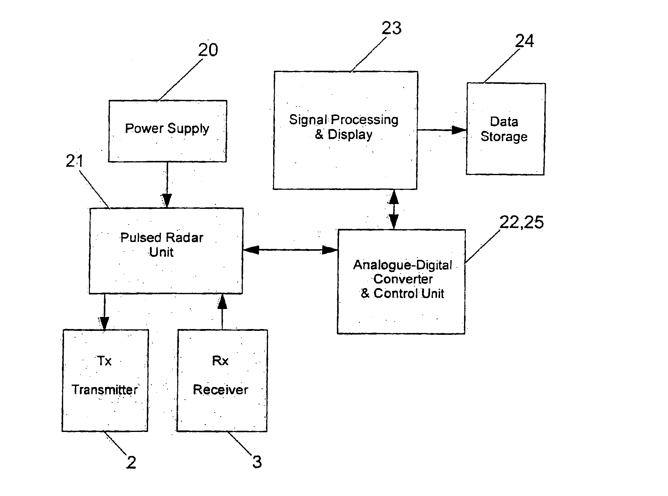
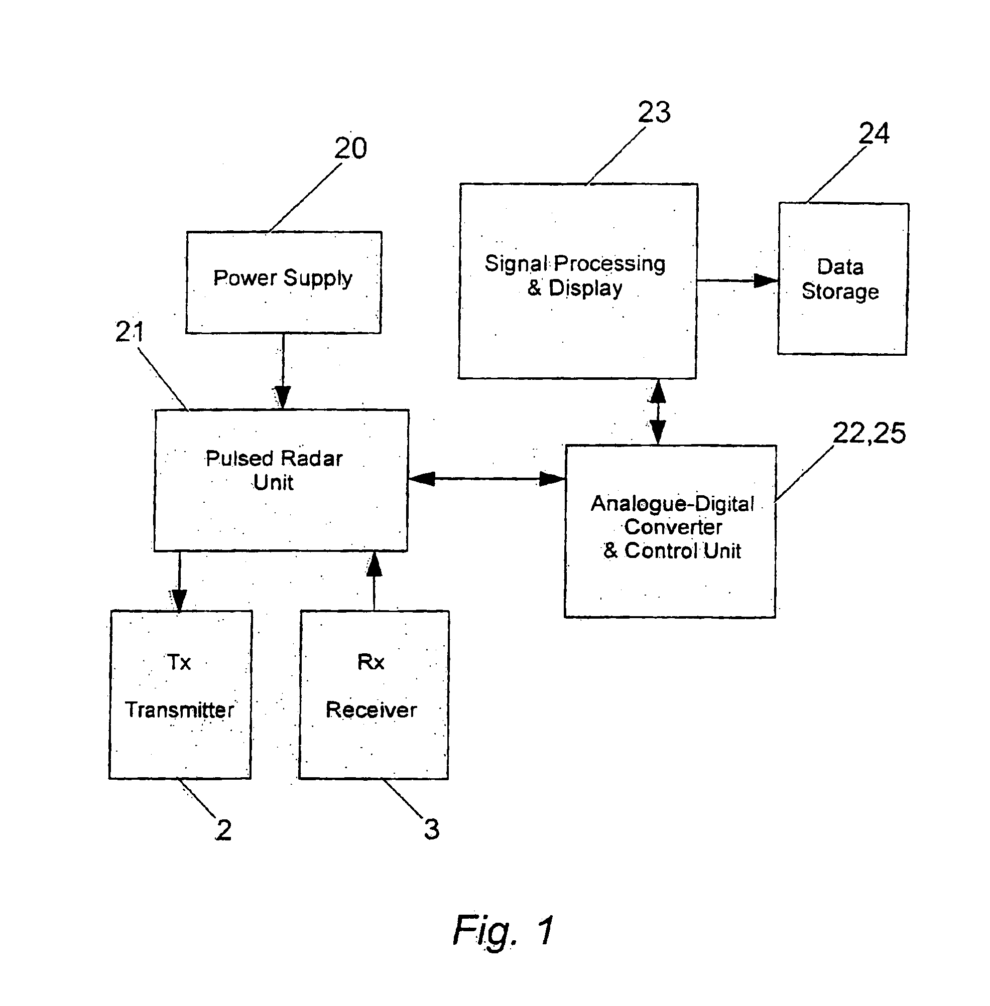
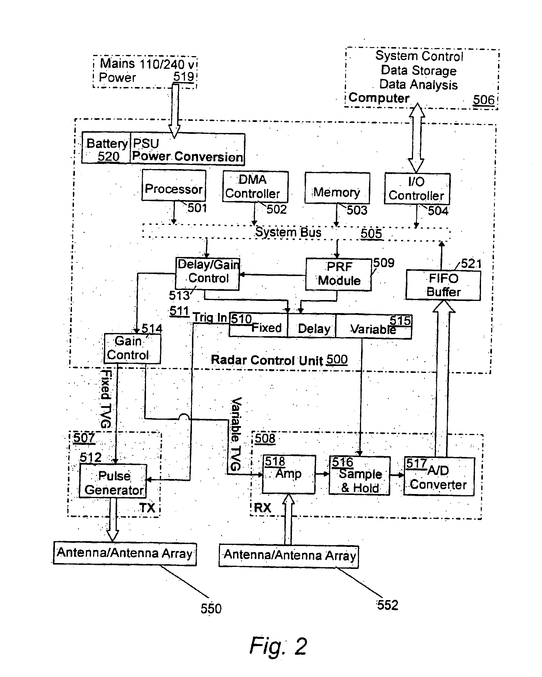
FIG. 1 is a generic block diagram illustrating the basic architecture of radar systems in accordance with the invention. A pulsed radar unit 21 is powered by a power supply 20. The radar unit 21 is connected to a transmitting (“Tx”) antenna assembly or antenna array2 and to a receiving (“Rx”) antenna assembly or antenna array 3. The radar unit 21 may be of a conventional type, suitably a Ground Penetrating Radar (GPR) set, capable of providing controlled signal pulses to the Tx antenna assembly 2 and of receiving and processing return signals received by the Rx antenna assembly 3 and includes suitable input / output means to transmit and receive pulsed signals. The general configuration, controls etc. of radar sets of this type will be well known to persons skilled in the art and will not be described in detail herein. The controls of the radar unit 21 enable the characteristics of the transmitted pulse to...


PUM

PropertyMeasurementUnit
frequencyaaaaaaaaaa
time rangeaaaaaaaaaa
frequencyaaaaaaaaaa

Abstract

Radar apparatus and methods of use thereof for imaging and / or spectrometric analysis. The invention employs pulsed radar signals for magnifying, imaging, scale measuring, identifying and / or typecasting the composition of substances by radargrammetric imaging and / or statistical analysis of energy / frequency spectrums. The invention may be used to locate and / or distinguish a substance from other substances, to image a substance / feature and to monitor the movement of an imaged substance / feature. The systems and methods can be adapted for a variety of applications at a wide range of scales and distances, from large scale, long range applications such as geophysical imaging / analysis, to the small scale such as material typecasting applications and small scale (including microscopic) imaging / analysis, including biological and medical imaging and diagnostic applications. The invention includes novel antenna assemblies and novel data processing techniques.

Description

BACKGROUND OF THE INVENTION(1) Field of the InventionThis invention relates to radar apparatus and methods of use thereof for imaging and / or spectrometric a analysis. In particular, it relates to pulsed radar apparatus for magnifying, imaging, scale measuring, identifying and / or typecasting the composition of a substance by radargrammetric imaging and / or spectrometric analysis. The invention further relates to the use of the radar apparatus to locate and / or distinguish a substance from other substances. The invention may additionally be used to image a substance / feature and to monitor the movement of an imaged substance / feature. Such moving substances / features include but are not limited to the flow of blood and other substances moving within a human or animal body, and substances / features in a subterranean environment, such as the movement of water, oil, gas and / or contaminants below the ground surface, below standing or flowing water bodies, or below sea level and the seabed.BRIEF...

Claims


Application Information

Patent Timeline
Patent Type & Authority Patents(United States)
IPC IPC(8): G01S13/00G01N22/00G01S13/89G01S13/88
CPCG01N22/00G01S13/89G01S13/885
Inventor STOVE, GEORGE COLIN
Owner STOVE GEORGE COLIN
Learn More