
Method for illuminating an object with light from a laser light source

a laser light source and object technology, applied in the direction of lasers, electric discharge lamps, instruments, etc., can solve the problems of inducing imaging aberration, high coherence length, undesired interference phenomena,

Inactive Publication Date: 2005-03-08
LEICA MICROSYSTEMS CMS GMBH
View PDF5 Cites 12 Cited by
  • Summary
  • Abstract
  • Description
  • Claims
  • Application Information

AI Technical Summary

Problems solved by technology

For some applications, however, a high coherence length is a problem since it can lead to the formation of undesired interference phenomena in the optical beam path.
Especially in confocal scanning microscopy, such interference phenomena can induce imaging aberrations.

Method used


Image

  • Method for illuminating an object with light from a laser light source
  • Method for illuminating an object with light from a laser light source
  • Method for illuminating an object with light from a laser light source

Examples


Embodiment Construction

It is therefore an object of the present invention to provide a method with which the coherence length of the laser light can be reduced, so that disruptive interference phenomena can be substantially eliminated. Should interference phenomena nevertheless be formed, these are to be influenced in such a way that they have no effect on the detection.

The method according to the invention of the generic type achieves the above object. According thereto, such a method is characterized in that the phase angle of the light field is varied by a modulator in such a way that interference phenomena do not occur in the optical beam path, or occur only to an undetectable extent, within a predeterminable time interval.

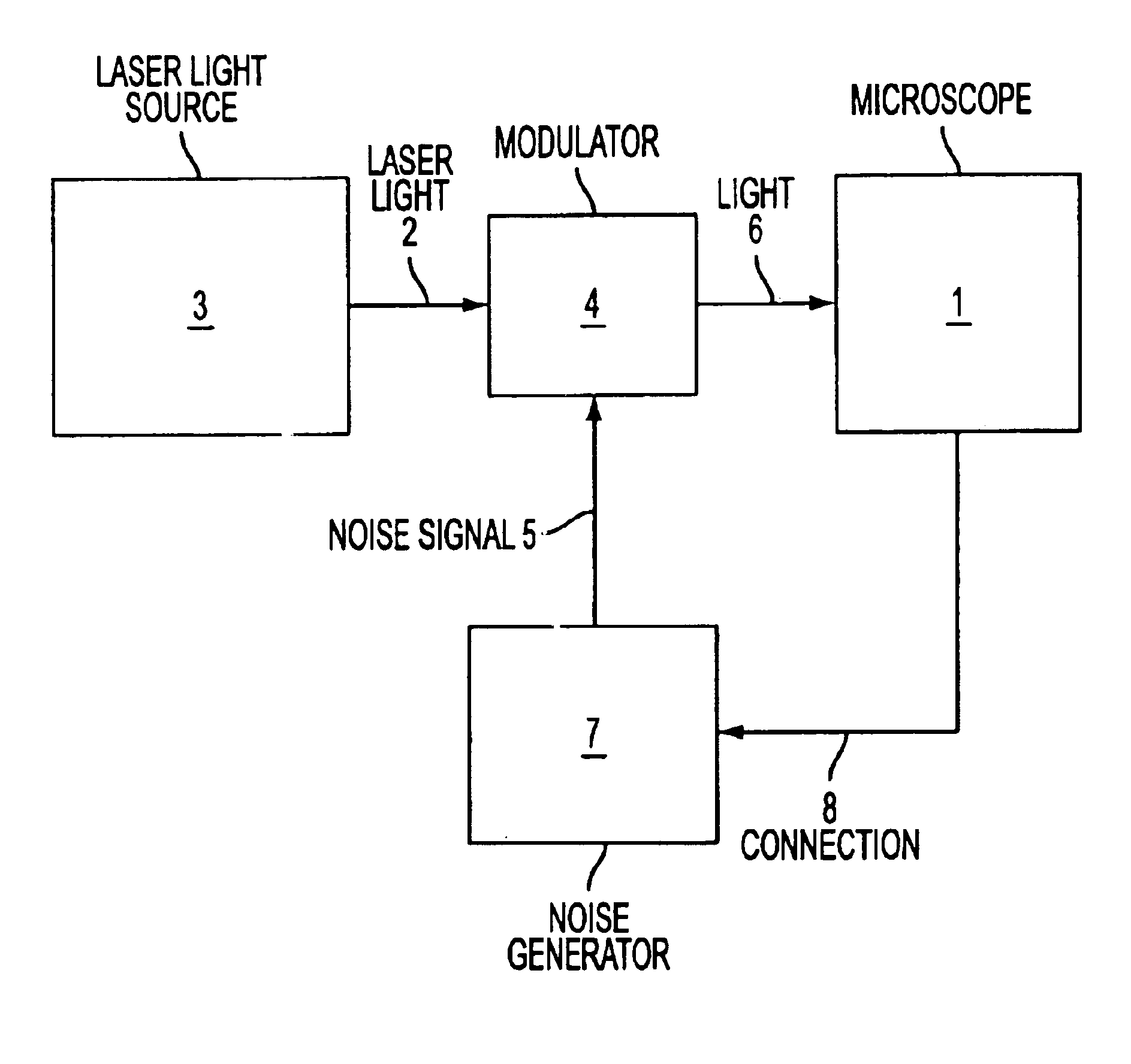
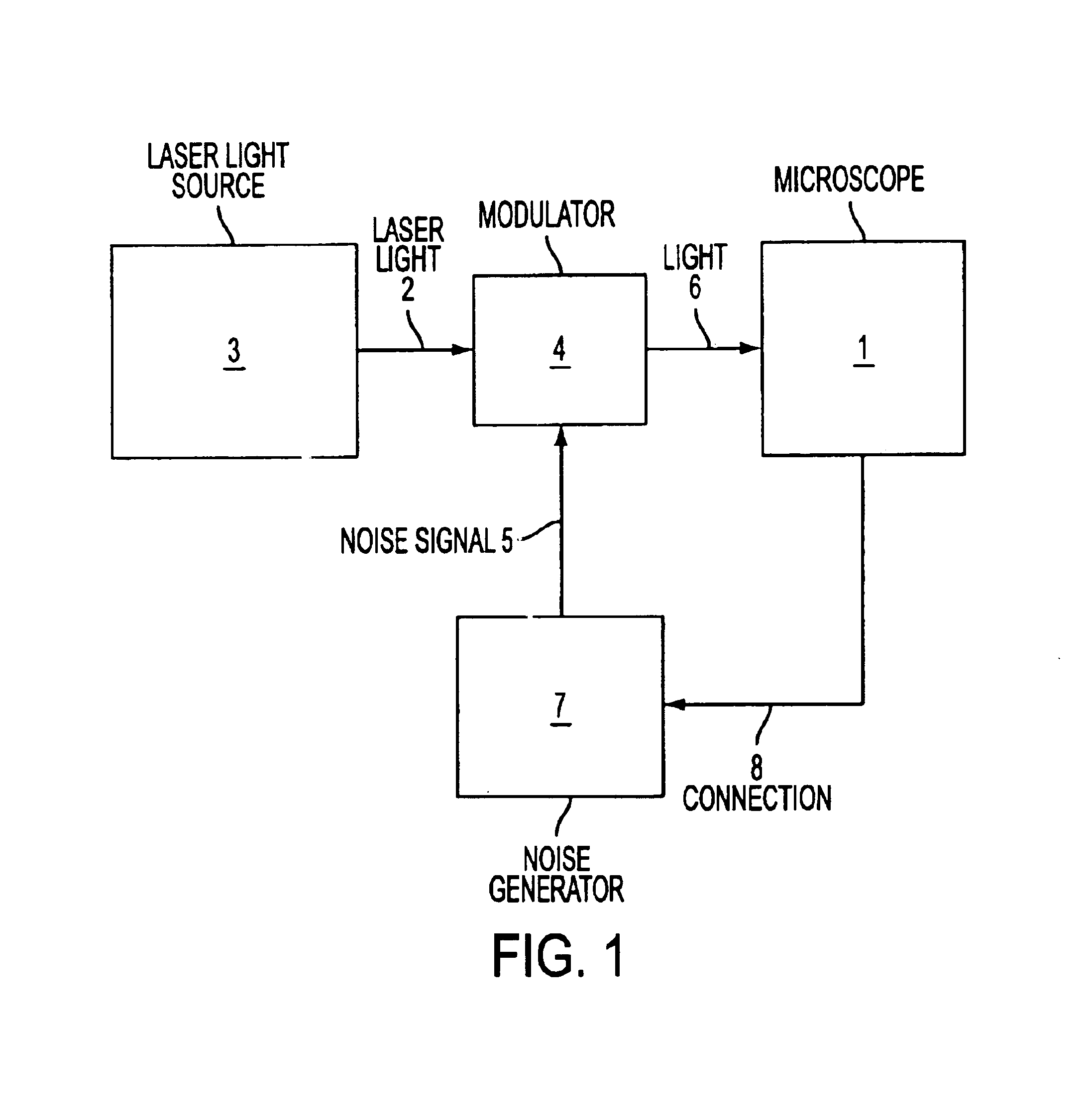
FIG. 1 shows a schematic representation of a confocal scanning microscope 1, in which an object is illuminated with light 2 from a laser light source 3. According to the invention, the phase angle of the light field is varied by a modulator 4 designed as an EOM, in such a way that i...


PUM


Abstract

A method for illuminating an object with light (2) from a laser light source (3), preferably in a confocal scanning microscope (1). With the method according to the invention, it is possible to reduce the coherence length of the laser light, so that disruptive interference phenomena can be substantially eliminated. Should interference phenomena nevertheless be formed, these are to be influenced in such a way that they have no effect on the detection. The method according to the invention is characterized in that the phase angle of the light field is varied by a modulator in such a way that interference phenomena do not occur in the optical beam path, or occur only to an undetectable extent, within a predeterminable time interval.

Description

CROSS REFERENCE TO RELATED APPLICATIONSThis invention claims priority of the German patent application 100 42 114.8 which is incorporated by reference herein.FIELD OF THE INVENTIONThe present invention relates to a method for illuminating an object with light from a laser light source, preferably in a confocal scanning microscope.BACKGROUND OF THE INVENTIONLaser light sources are used in a large number of devices and applications for illuminating objects. In this case, in particular, the advantages of high coherence length and excellent beam profile, i.e. parallelism of the light radiation emitted by the laser light source, the outstanding frequency or wavelength consistency, and the monochromaticity of the light are utilized.The high spatial and temporal coherence of laser light is due to the stimulated emission by the optical medium in the laser, and has the effect that both the individual wavelets and the waves emitted at different times interfere virtually without limitation. Th...

Claims


Application Information

Patent Timeline
IPC IPC(8): G02B21/00G02B26/06G02B21/06G02F1/01H01S3/00
CPCG02B21/0056G02B21/0024
Inventor STORZ, RAFAELENGELHARDT, JOHANNBIRK, HOLGER
Owner LEICA MICROSYSTEMS CMS GMBH
Learn More