Method of manufacturing a stator for an alternator with reduced conductor portions

a technology of conductors and stators, which is applied in the manufacture of stators/rotors, magnets, and magnetic bodies, etc., can solve the problems of difficult coil inserting, insulation defects, insulating paper, etc., and achieve the effect of improving productivity and reliability

Inactive Publication Date: 2005-03-15
MITSUBISHI ELECTRIC CORP
View PDF18 Cites 66 Cited by
  • Summary
  • Abstract
  • Description
  • Claims
  • Application Information

AI Technical Summary

Benefits of technology

The present invention aims to solve the above problems, and an object of the present invention is to provide a stator for an alternator and a method of manufacturing the stator enabling...

Problems solved by technology

Because the bulges A and burrs B extend beyond the profile of the coil members 29, when the coil segments 30 are being inserted into the slots 15b, the bulges A catch and make it difficult to insert the coil into the slots, and the burrs B damage the insulating paper 19 giving rise to insulation defects.
Thus, one problem has been reduced productivity and reliability.
Because the insulation coating on the free end portions 30c of the coil segments 30 is not removed, welding deteriorates, giving rise to dislodgement of the joint portions due to vibrations from the engine, etc., causing problems which reduce reliability.
As a result, when welding the free end portions 30c of the two coil segments 30 on the inner circumferential side, for example, there is a risk that the heat of welding will be transferred to the free end portions 30c of the coil segments 30 on the outer circumferential side and weld them to t...

Method used


Image

  • Method of manufacturing a stator for an alternator with reduced conductor portions
  • Method of manufacturing a stator for an alternator with reduced conductor portions
  • Method of manufacturing a stator for an alternator with reduced conductor portions

Examples


embodiment 1

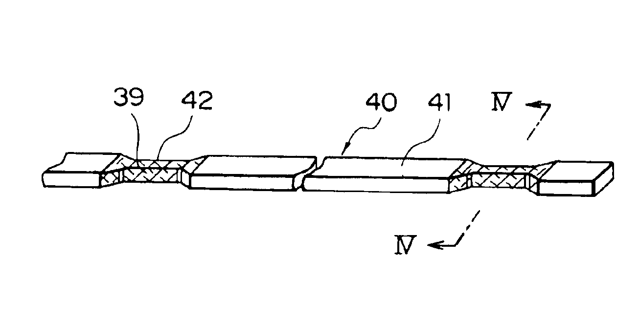
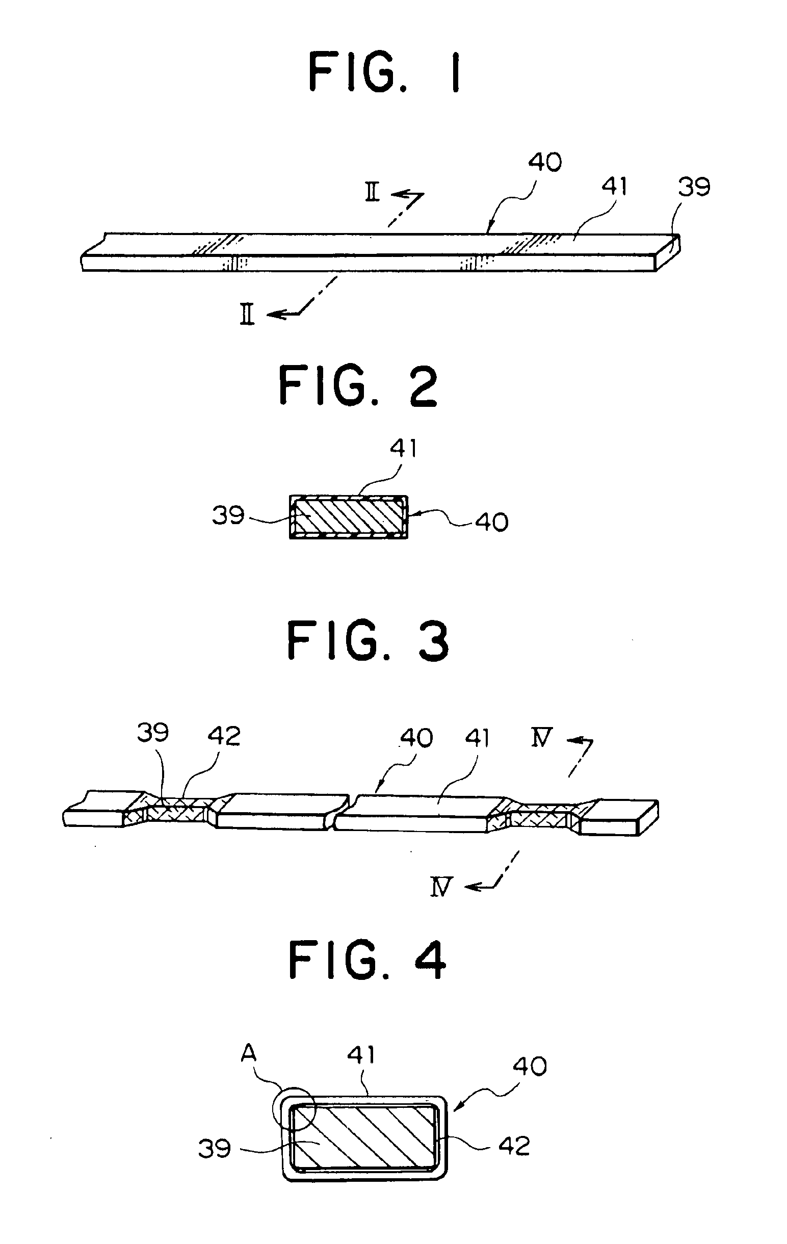
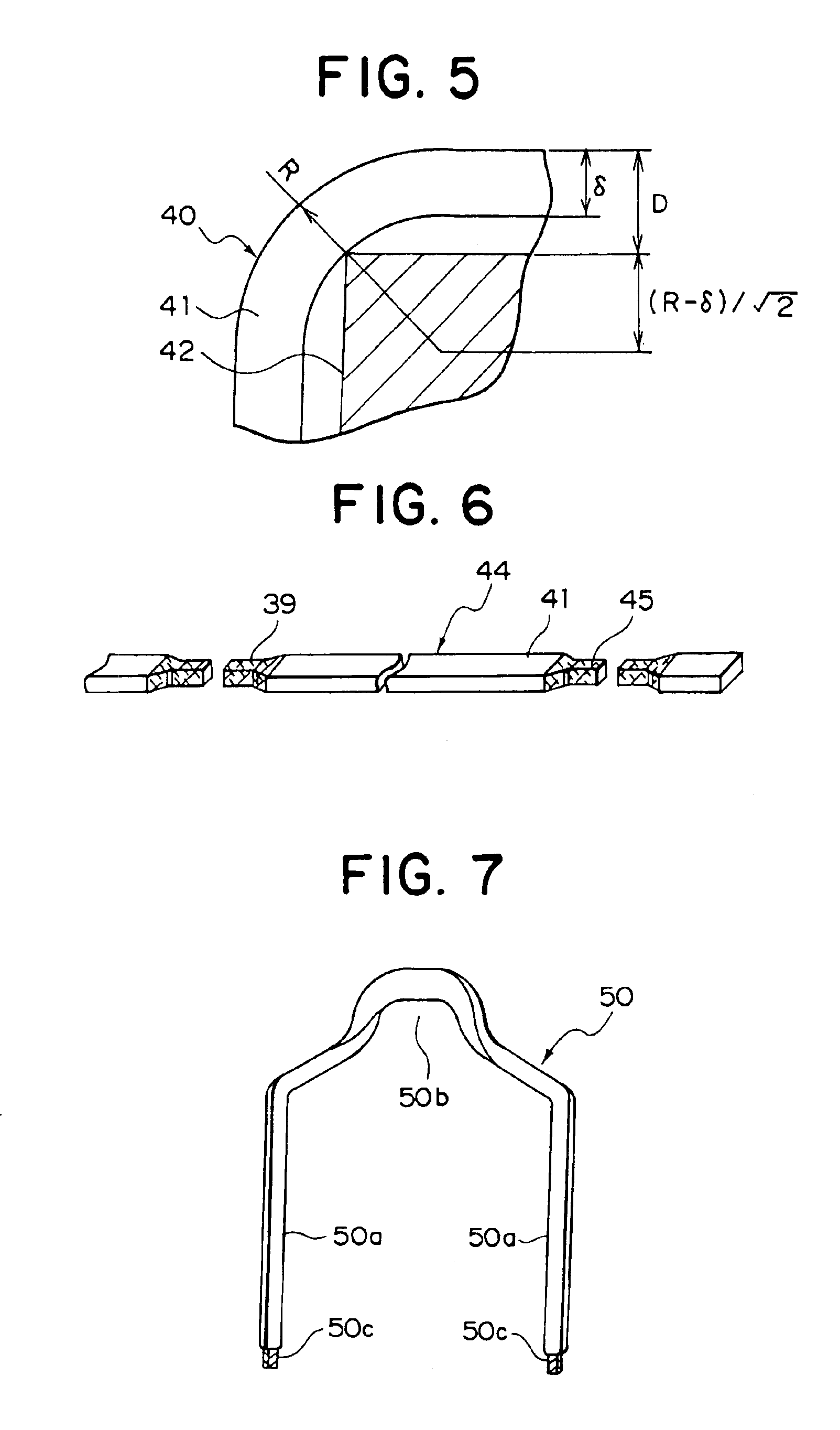
FIG. 1 is a perspective showing wire material used in a stator coil of a stator for an alternator according to Embodiment 1 of the present invention, FIG. 2 is a cross section taken along line II—II in FIG. 1, FIG. 3 is a perspective showing reduced outer portions formed in the wire material in a method for manufacturing the stator for an alternator according to Embodiment 1 of the present invention, FIG. 4 is a cross section taken along line IV—IV in FIG. 3, FIG. 5 is an enlargement of portion A in FIG. 4, FIG. 6 is a perspective showing coil members formed by cutting the wire material in the method for manufacturing the stator for an alternator according to Embodiment 1 of the present invention, FIG. 7 is a perspective showing a coil segment formed by applying a bending process to a coil member in the method for manufacturing the stator for an alternator according to Embodiment 1 of the present invention, FIGS. 8 and 9 are an end elevation and a side elevation, respectively, expla...

embodiment 2

FIG. 15 is a perspective showing width-reduced portions formed in a wire material in a method for manufacturing a stator for an alternator according to Embodiment 2 of the present invention, FIG. 16 is a cross section taken along line XVI—XVI in FIG. 15, and FIG. 17 is a perspective showing width-reduced portions of wire material with insulation coating removed in a method for manufacturing a stator for an alternator according to Embodiment 2 of the present invention.

Embodiment 2 is constructed similarly to Embodiment 1 above except for the fact that width-reduced portions 43A are formed in the wire material 40 using a press-cutting method instead of a machining process.

As shown in FIGS. 15 and 16, in Embodiment 2, the width-reduced portions 43A are formed by cutting the electrical conductor 39 on both sides of the wire material 40 together with the insulation coating 41 in the width direction over a predetermined range in the longitudinal direction at predetermined distances using ...

embodiment 3

In Embodiments 1 and 2 above, the insulation coating 41 was removed by applying a machining process to the upper and lower surfaces of the width-reduced portions formed at predetermined distances along the wire material 40, but in Embodiment 3, the insulation coating 41 is burned by directing a flame onto the width-reduced portions of the wire material 40, and then carbides formed by burning the insulation coating 41 are removed by brushing.

According to Embodiment 3, because the insulation coating 41 is burned by a flame, the insulation coating can be removed simply and reliably without contact. Thus, unremoved insulation coating is eliminated from the weld portions, preventing in advance poor weldability as a result of such remnants.


PUM

PropertyMeasurementUnit
Thicknessaaaaaaaaaa
Electrical conductivityaaaaaaaaaa
Shapeaaaaaaaaaa

Abstract

Coil members are obtained by forming width-reduced portions in a wire material over a predetermined longitudinal range generally centered on cutting positions, then removing an insulation coating from the width-reduced portions, and thereafter cutting the wire material at the width-reduced portions. Coil segments are prepared by bending the coil members into a general U shape. Then the coil segments are inserted into the slots in a stator core, and a stator is obtained by welding together the free end portions of the projecting coil segments.

Description

BACKGROUND OF THE INVENTION1. Field of the InventionThe present invention relates to a stator for an alternator driven by an internal combustion engine, for example, and to a method for manufacturing the stator, and in particular, relates to a stator for an alternator and a method for the manufacture thereof in which the stator is provided with a stator coil constructed by installing coil wires having a flat cross section formed into a predetermined shape into a stator core, and welding together end portions of the coil wires.2. Description of the Related ArtFIG. 38 is a cross section showing the construction of a generic alternator.The conventional alternator includes: a Lundell-type rotor 7 mounted so as to rotate freely by means of a shaft 6 within a case 3 composed of an aluminum front bracket 1 and an aluminum rear bracket 2; and a stator 8 secured to the inner wall of the case 3 so as to cover the outer circumference of the rotor 7.The shaft 6 is rotatably supported by the fro...

Claims


Application Information

Patent Timeline
IPC IPC(8): H02K3/12H02K15/00H02K15/06H02K15/04H02K3/38H02K3/04H02K15/02
CPCH02K3/12H02K15/0056H02K15/0081H02K15/0478H02K15/066H02K15/064Y10T29/53143Y10T29/49009Y10T29/49071H02K15/02
Inventor OOHASHI, ATSUSHIASAO, YOSHIHITOADACHI, KATSUMITAKIZAWA, TAKUSHI
Owner MITSUBISHI ELECTRIC CORP
Why Eureka
Try Eureka