Drain catheters

a catheter and lumen technology, applied in catheters, intravenous devices, infusion needles, etc., can solve the problems of reducing the effectiveness of the drain, and the patient's body

Inactive Publication Date: 2005-03-15
SHCHERVINSKY SEMYON
View PDF14 Cites 90 Cited by
  • Summary
  • Abstract
  • Description
  • Claims
  • Application Information

AI Technical Summary

Problems solved by technology

A significant problem with wound drain catheters is that wound debris, such as clots, may block the apertures thereby reducing the effectiveness of the drain.
Another problem is that as the wound heals, tissue tends to form in the apertures of the wound drain catheter further reducing the effectiveness of the drain.
In addition, when the wound drain catheter is removed from the patient, such as by applying a pulling force, any tissue that has grown into the apertures will be torn from the patient's body causing discomfort and retarding the healing process.
If tissue growth into the apertures is extensive, the drain may break during removal thereby leaving a portion of the drain in the patient's body requiring additional surgery.
Other wound drain catheters have flat or round elongated channel shapes with a solid core, however, these channels tend to become easily clogged.
Furthermore, when these drain catheters are removed such as by pulling, the diameter of the catheter decreases and gaps between channels causes pinching thereby trapping tissue during drain removal.
This type of drain is limited in use and is specifically designed to remove blood and secretion during a surgical incision, whereby the tip is connected to a high vacuum source.
This type of drain is limited in use and is specifically designed to flush the urethra, is not for use in post-surgical drainage, and is always exposed to infection.
This type of drain has limit of use and is specifically design to the atmosphere, rather than to an outflow tube and always exposed to infection causing organism.

Method used


Image

  • Drain catheters
  • Drain catheters
  • Drain catheters

Examples


Embodiment Construction

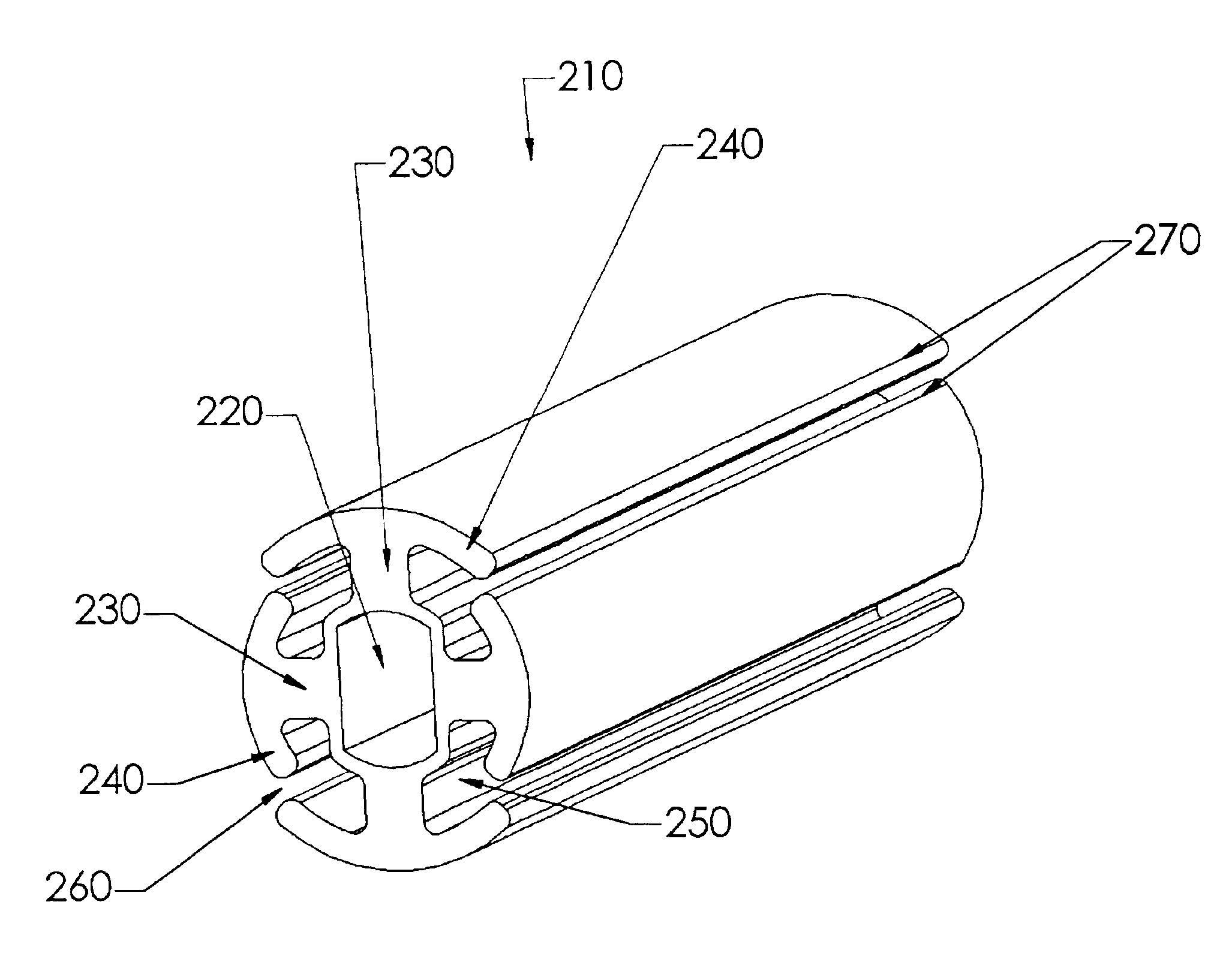
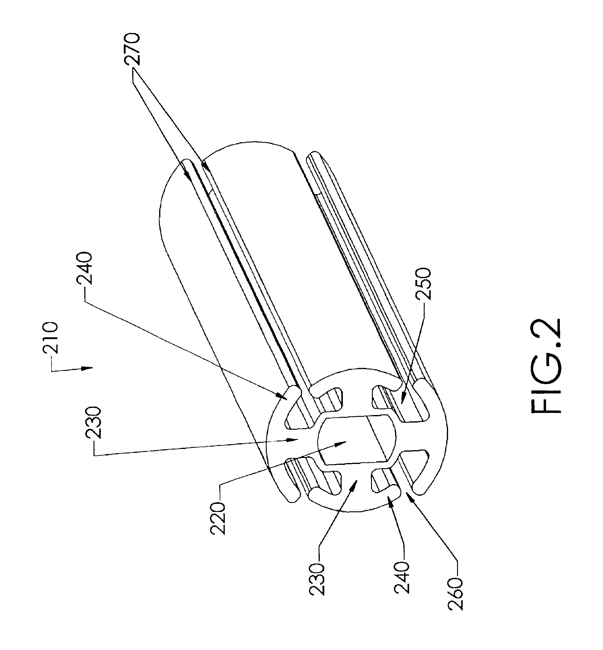
The present invention comprises a wound drain catheter for draining fluid from, or supplying medication to, a wound in a patient. The drain of the present invention provides an increased tissue contact drainage area and an increased lumenal flow drainage area compared to prior art drains. Further, the specific configuration of this wound drain catheter provides an increased drain body cross-sectional area and eliminates weak points in the drain body. This configuration makes the wound drain catheter of the present invention stronger than comparably sized drains and therefore less likely to break during removal. Moreover, the present drain configuration reduces the risk that tissue growth will inhibit removal of the drain. Thus, the drain provides safety, reliability, and effectiveness not found in prior art drains.

The wound drain catheters of the present invention are fluted and comprise a hollow central core with radially projecting strut portions. The radial strut portions may or ...


PUM


Abstract

The present invention is directed to a wound drain catheter for draining fluid from, or supplying medication to, a wound in a patient. The wound drain catheter comprises a drain, a flexible outflow tube, and means for connecting the drain to the flexible outflow tube. The drain comprises a hollow core having a longitudinal axis; plural struts extending outwardly from the hollow core and being closed to the hollow core; and plural overhangs connected to the outward ends of the struts, respectively, the overhangs cooperating with the struts to form plural longitudinal lumens, the overhangs cooperating with each other to form, on the outer surface of the drain, segments of a segmented, closed curve with gaps between the segments providing plural longitudinal grooves for fluid communication between the wound and a respective lumen, the grooves sized to inhibit tissue from growing therein and debris from passing therethrough. The present invention also includes a method for draining fluid from, or supplying medication to, a wound in a patient.

Description

FIELD OF THE INVENTIONThe present invention relates to multilumen wound drain catheters for removing fluids from a wound. The wound drain catheters may also be used to supply medication to a wound.DESCRIPTION OF THE BACKGROUNDWound drain catheters for draining closed wounds generally comprise a drain portion in fluid communication with a wound and an outflow tube for transporting fluid from the drain to a reservoir. Typically, the outflow tube is connected to a vacuum source after the drain has been placed in the wound and the wound has been closed. The most common type of wound drain catheter is a tubing perforated with spaced apertures through the tubing wall. The spaced apertures are usually in opposed pairs and the spacing between the aperture pairs may vary. A significant problem with wound drain catheters is that wound debris, such as clots, may block the apertures thereby reducing the effectiveness of the drain. Another problem is that as the wound heals, tissue tends to form...

Claims


Application Information

Patent Timeline
Patent Type & Authority Patents(United States)
IPC IPC(8): A61M27/00A61M1/00A61M25/00
CPCA61M1/008A61M27/00A61M25/0021A61M1/84
Inventor SHCHERVINSKY, SEMYON
Owner SHCHERVINSKY SEMYON
Why Eureka
Try Eureka