

Apparatus for removing plaque from blood vessels using ultrasonic energy
- Summary
- Abstract
- Description
- Claims
- Application Information
AI Technical Summary
Benefits of technology
Problems solved by technology
Method used
Image

Examples
Embodiment Construction
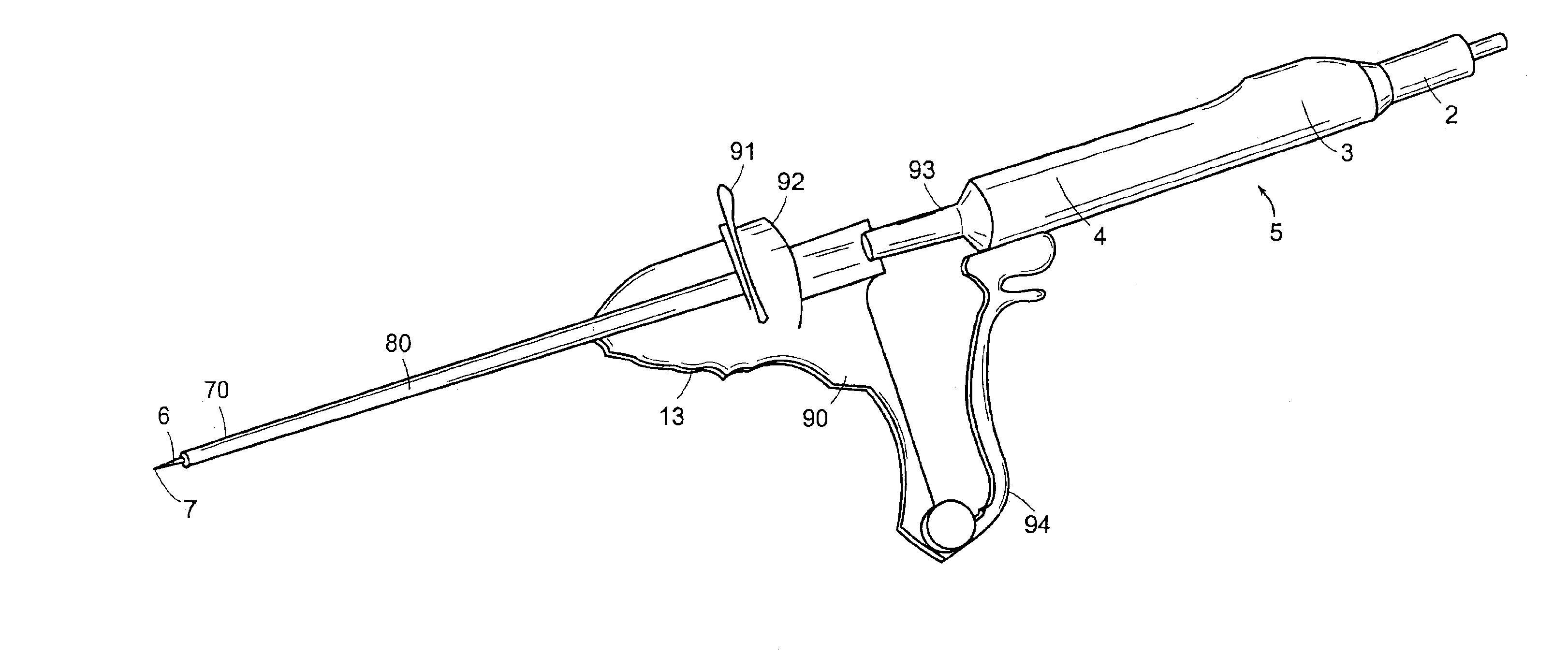
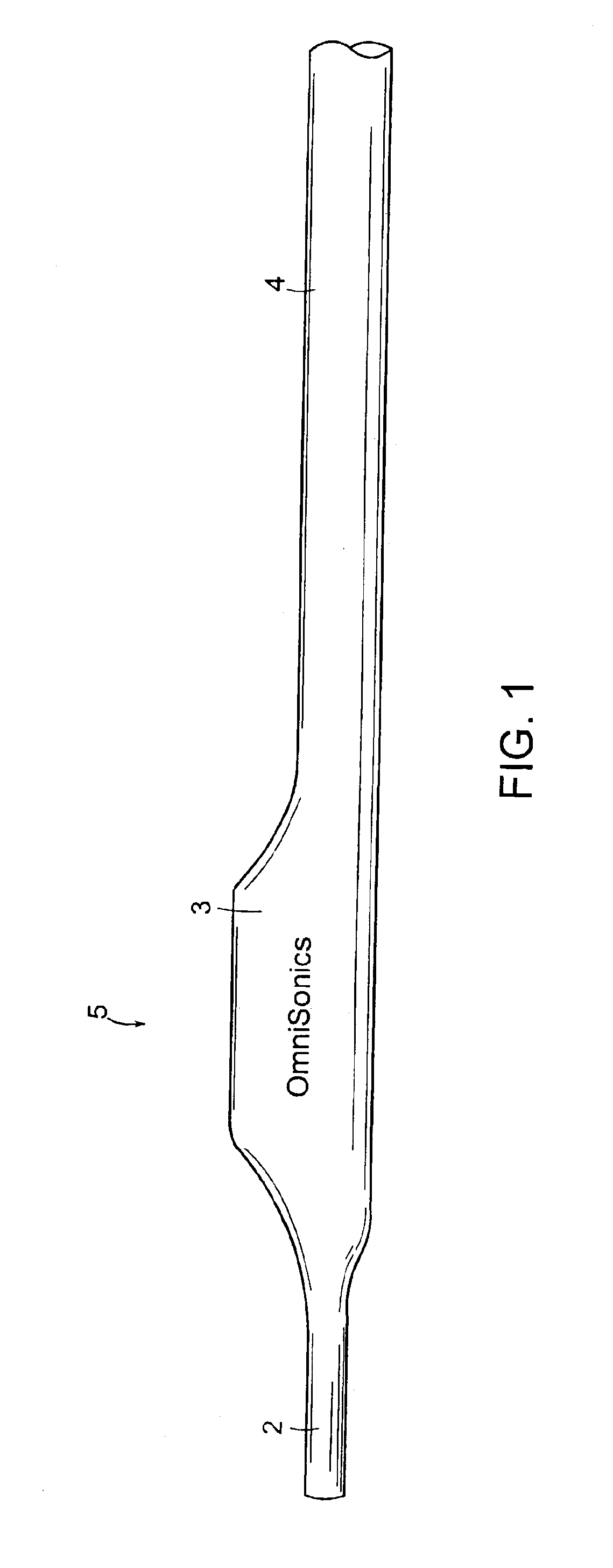
[0056]FIG. 1 shows an embodiment of a handle 5 used with the present invention. The handle 5 is composed of an irrigation fitting or luer 2, a grasping area 3, and a probe fitting 4. The irrigation fitting or luer 2 is configured for connection with a flexible tube which is in turn connected to a source of pressurized irrigating fluid, such as water. The grasping area 3 is shaped for grasping by the hand of the apparatus operator, such as a surgeon, and may include one or more trigger or button mechanisms for activating and deactivating various features of the apparatus, such as suction, irrigation, power, etc.
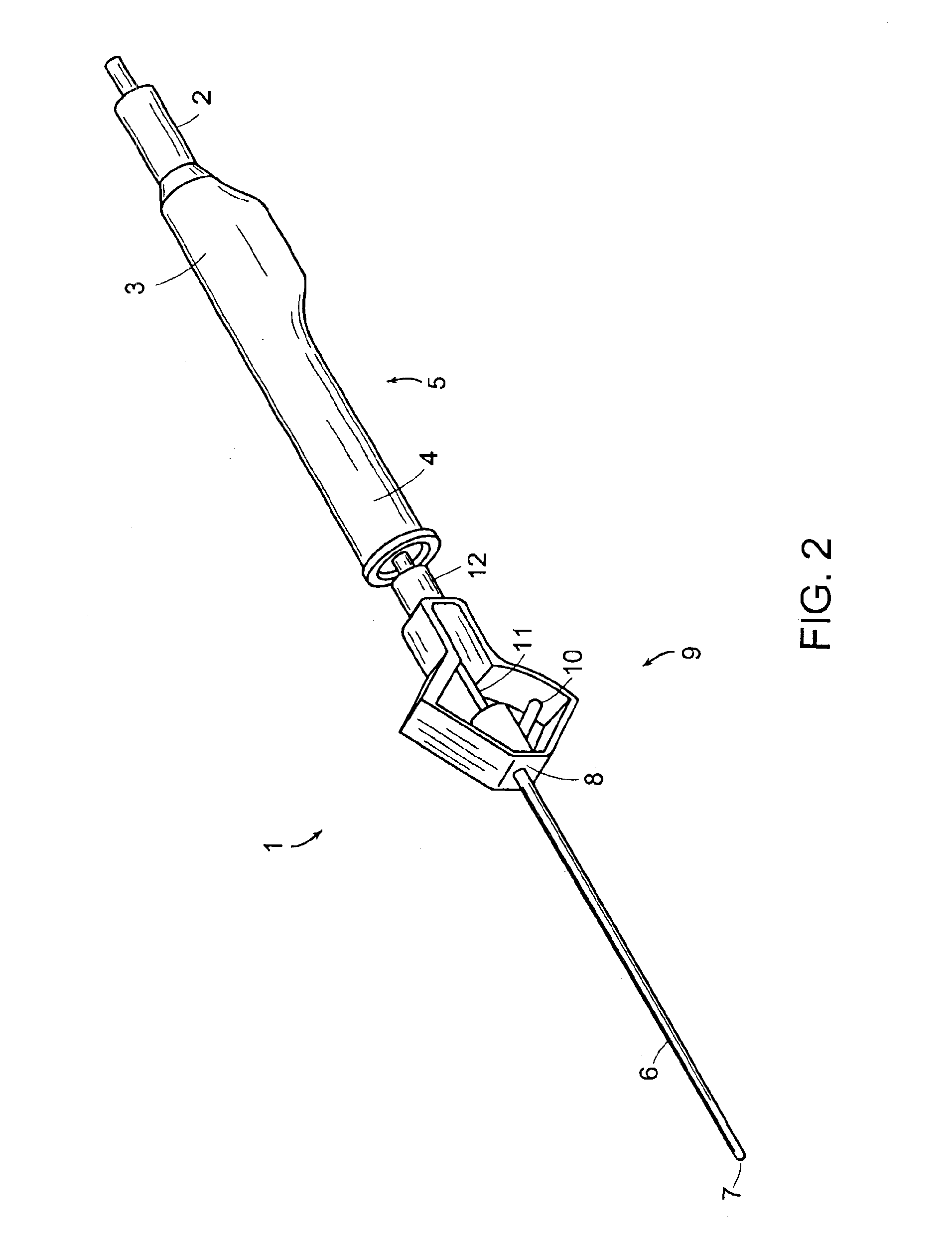
[0057]FIGS. 2 and 3 show an embodiment of the ultrasonic treatment apparatus 1 of the present invention, which includes the handle 5 shown in FIG. 1. The ultrasonic treatment apparatus 1 includes an ultrasonic probe 6 with an ultrasonic probe tip 7. The ultrasonic probe 6 is axially movably mounted within an aspiration sheath or catheter 70, so that the probe tip 7 may move ax...
PUM
 Abstract
Description
Claims
Application Information