
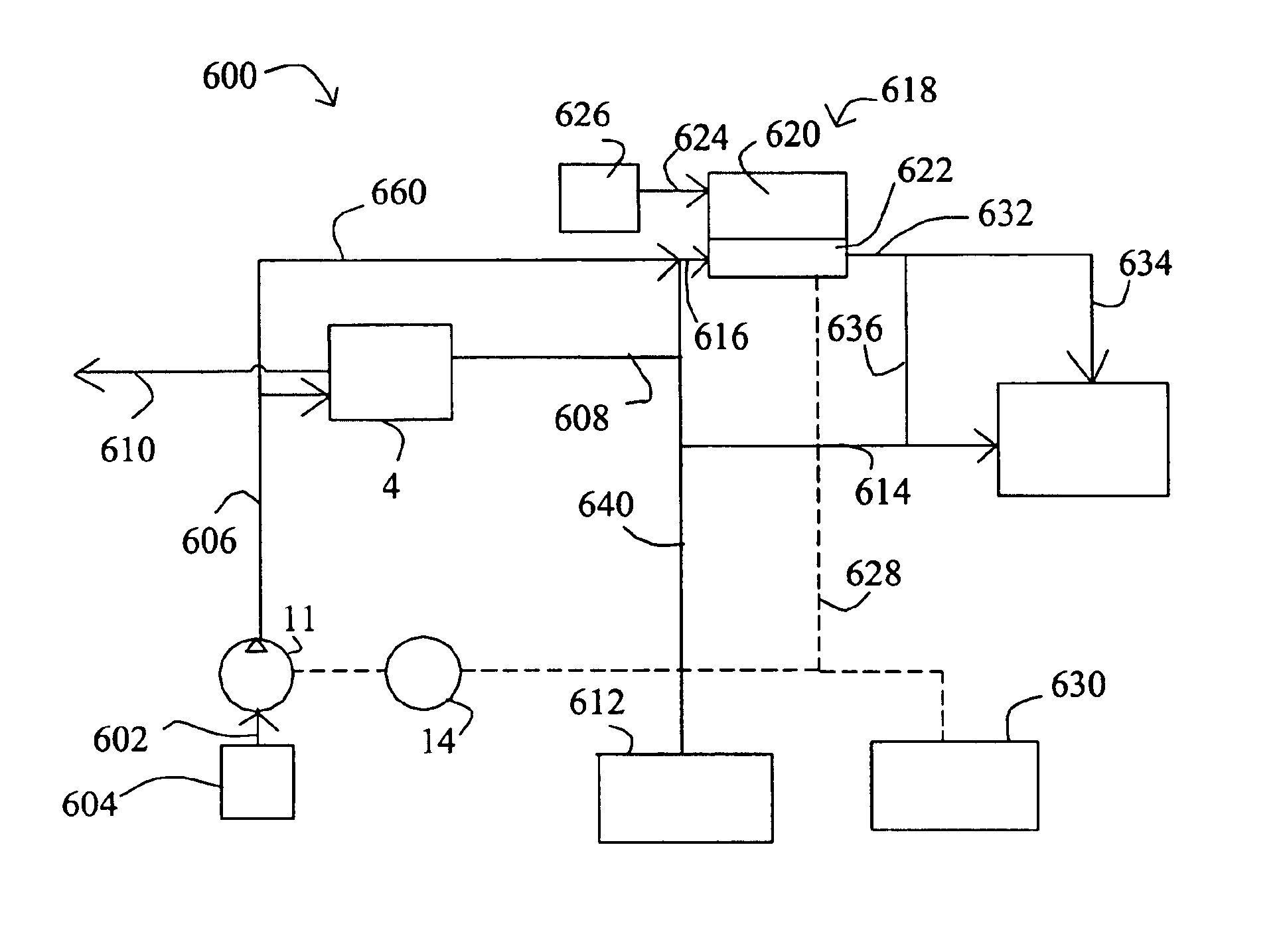
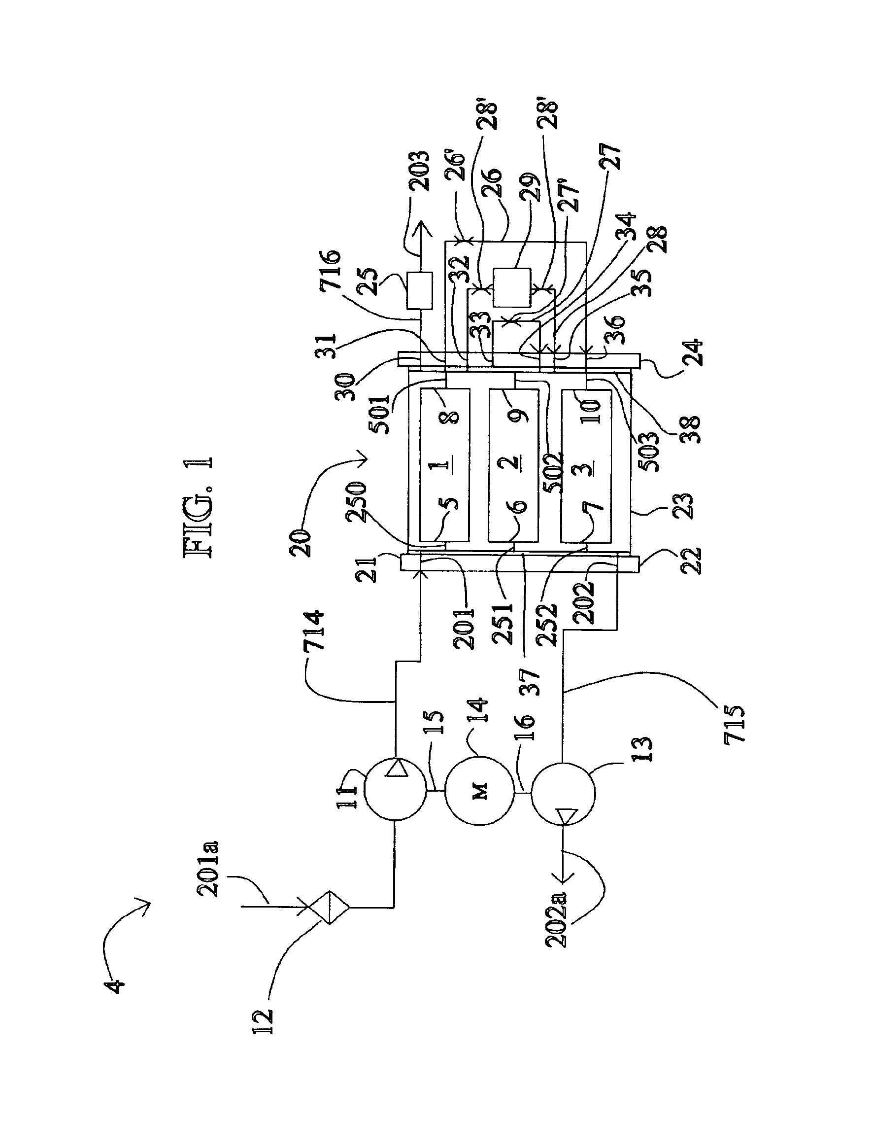
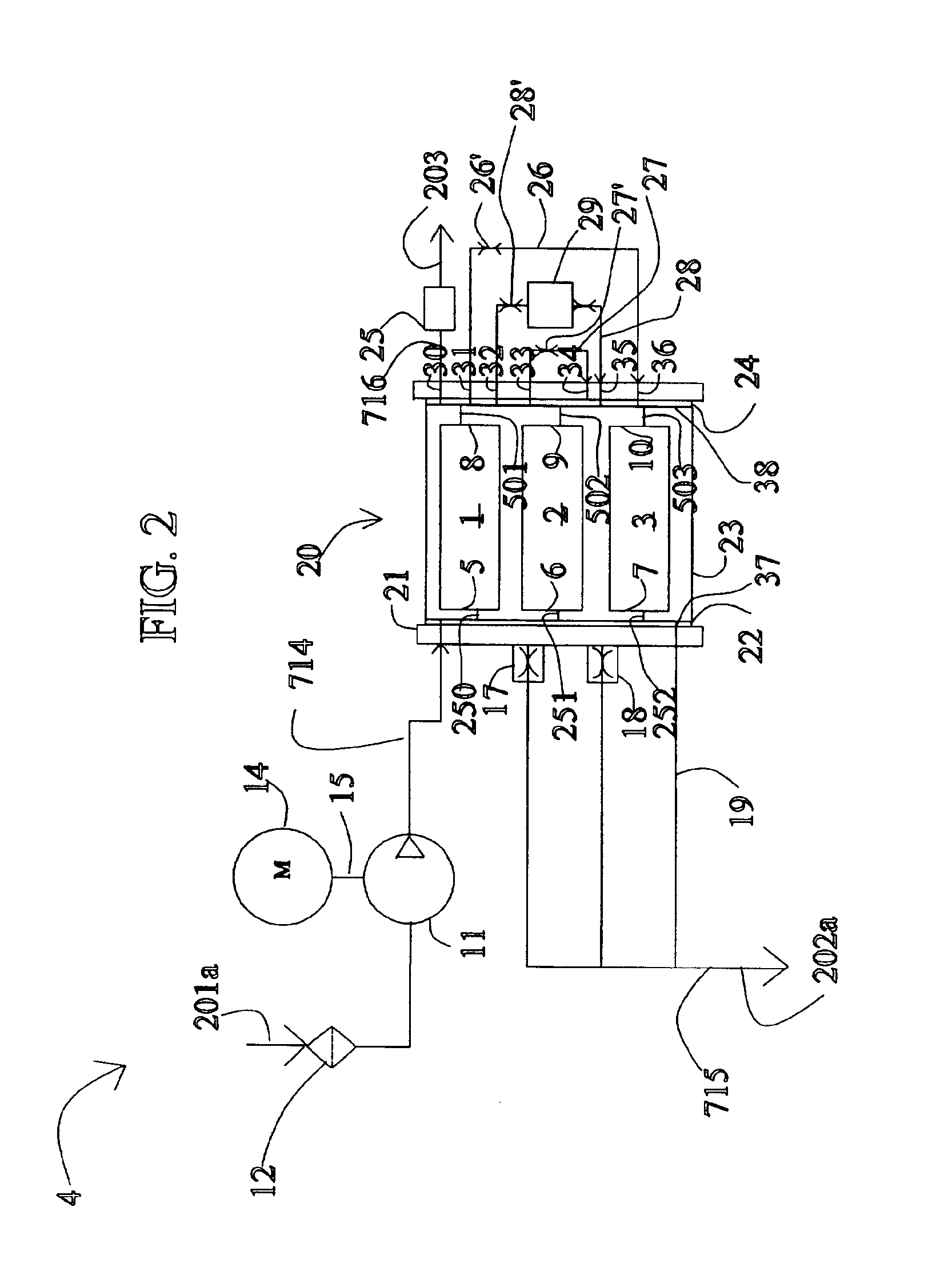
Methods and apparatuses for gas separation by pressure swing adsorption with partial gas product feed to fuel cell power source

a gas product and gas separation technology, applied in the direction of separation process, dispersed particle separation, electrochemical generator, etc., can solve the problems of inefficient application of applied energy in the basic pressure swing adsorption process, affecting process efficiency, and affecting process efficiency

Inactive Publication Date: 2005-03-15
AIR PROD & CHEM INC
View PDF140 Cites 141 Cited by
  • Summary
  • Abstract
  • Description
  • Claims
  • Application Information

AI Technical Summary

Benefits of technology

The patent describes various systems, methods, and apparatuses for separating components in a feed gas to provide an oxygen-enriched concentrated gas stream. The systems include a pressure swing adsorption apparatus powered by a fuel cell and can be used to deliver the concentrated gas to a human being. The methods involve introducing a feed gas into the pressure swing adsorption apparatus to produce a product gas that is enriched in oxygen relative to air, and using the fuel cell to generate an electrical current to power the pressure swing adsorption apparatus. The technical effects of the patent include the ability to provide a safe and efficient means for delivering oxygen-enriched gas to a human being for therapeutic or other purposes.

Problems solved by technology

The basic pressure swing adsorption process inefficiently uses applied energy, because of irreversible expansion over the valves while switching the adsorbers between higher and lower pressures.
The conventional method of supporting the adsorbent is also problematic.
(U.S. Pat. No. 5,411,528), but in each of these latter examples there is some undesirable inversion of the ordering of light product withdrawal and light reflux steps so that process efficiency is compromised.
Portable gas separators, such as might be used for generating oxygen of sufficient purity for respiration by mammals, such as humans, such as greater than 90 volume % pure, and perhaps 95 volume % and higher, are inefficient and typically are not easily portable by an individual.
As such, the uses of conventional separators are limited.

Method used


Image

  • Methods and apparatuses for gas separation by pressure swing adsorption with partial gas product feed to fuel cell power source
  • Methods and apparatuses for gas separation by pressure swing adsorption with partial gas product feed to fuel cell power source
  • Methods and apparatuses for gas separation by pressure swing adsorption with partial gas product feed to fuel cell power source

Examples


Embodiment Construction

Disclosed embodiments are described below with reference to the drawings. Definitions of certain terms, and general information concerning certain features of the disclosed embodiments, are provided below.

The following definitions are provided solely to aid the reader, and should not be construed to have a scope less than that understood by a person of ordinary skill in the art or as limiting the scope of the appended claims.

A. “Backfill” denotes feeding a portion of the oxygen-enriched gas to the product end of the bed. The feed end of the bed is closed during this operating step thus increasing the pressure in the bed.

B. “Blowdown” refers to a process where gas is being removed from a feed end of the bed (countercurrent) direction. The product end is closed. A vacuum pump is connected to the feed end of the bed and bed pressure is reduced.

C. “Cocurrent direction” is when the gas flows from a feed end to a product end.

D. “Countercurrent direction” is when the gas flows from a produ...


PUM

PropertyMeasurementUnit
volume percentaaaaaaaaaa
pressureaaaaaaaaaa

Abstract

Various systems, method and apparatuses are disclosed that include a pressure swing adsorption apparatus coupled to a fuel cell, wherein the fuel cell receives at least a portion of a product gas from the pressure swing adsorption and powers the pressure swing adsorption apparatus. Also disclosed is a portable gas separator that include a housing that houses a rotary pressure swing adsorption apparatus.

Description

FIELDThis disclosure concerns gas separations conducted by pressure swing adsorption (PSA), such as air separation or air purification.BACKGROUNDI. Pressure Swing AdsorptionGas separation by pressure swing adsorption is achieved by coordinated pressure cycling and flow reversals over an adsorber contacted with a gas mixture that preferentially adsorbs a more readily adsorbed component relative to a less readily adsorbed component of the mixture. The total pressure is elevated during intervals of flow in a first direction through the adsorber from a first end to a second end, and is reduced during intervals of flow in the reverse direction. As the cycle is repeated, the less readily adsorbed component is concentrated in the first direction, while the more readily adsorbed component is concentrated in the reverse direction.A first, or “light,” product, depleted in the more readily adsorbed component and enriched in the less readily adsorbed component, is delivered from a second end of...

Claims


Application Information

Patent Timeline
Patent Type & Authority Patents(United States)
IPC IPC(8): B01D53/047H01M8/06H01M8/04
CPCB01D53/047B01D53/06H01M8/04089H01M8/0612B01D53/0476Y02E60/50B01D53/053B01D2253/108B01D2256/10B01D2256/12B01D2257/102B01D2257/104B01D2258/0208B01D2259/40005B01D2259/40009B01D2259/40015B01D2259/4003B01D2259/40032B01D2259/40066B01D2259/40067B01D2259/403B01D2259/4533B01D2259/4541
Inventor CONNOR, DENIS J.KEEFER, BOWIE G.MCLEAN, CHRISTOPHER R.KNIGHTS, SHANNA D.ST-PIERRE, JEAN
Owner AIR PROD & CHEM INC
Learn More