Eddy current inspection probe for inspecting multiple portions of a turbine blade having different geometric surfaces

a technology turbine blade, which is applied in the direction of magnetic measurement, measuring devices, instruments, etc., can solve the problems of eddy current probe, inability to reach all blades within the turbine that need to be inspected, and difficult blade inspection, so as to minimize the amount of non-productive downtime of the turbin

Inactive Publication Date: 2005-03-15
SIEMENS ENERGY INC
View PDF3 Cites 18 Cited by
  • Summary
  • Abstract
  • Description
  • Claims
  • Application Information

AI Technical Summary

Benefits of technology

By selecting an appropriate inspection tip, and possibly an appropriate shaft extension, the inspection shaft may be configured to reach most or all portions of the turbine blades through one of the inspection ports provided on a turbine. The video probe permits the inspector to precisely position the probe tip in the location desired, thereby insuring that all surfaces requiring inspection are actually inspected. By housing the electronic signal cables for both the eddy current probe and video camera within the main shaft portion, the risk of damage to these components during inspection of a turbine is minimized. By eliminating the need to disassemble the turbine to perform the inspection, the amount of nonproductive downtime for the turbine is minimized.

Problems solved by technology

The inaccessibility and small size of the open space within the combustion turbine, and between and among the turbine blades, makes inspection of the blades difficult without partial disassembly of the turbine.
Presently available eddy current probes, configured for insertion through the inspection ports on the turbine, are unable to reach all portions of a blade within the turbine that need to be inspected.
Additionally, it is difficult to determine the exact location of such probes within the turbine, thereby creating a possibility that certain regions that need to be inspected will be missed during the inspection.

Method used


Image

  • Eddy current inspection probe for inspecting multiple portions of a turbine blade having different geometric surfaces
  • Eddy current inspection probe for inspecting multiple portions of a turbine blade having different geometric surfaces
  • Eddy current inspection probe for inspecting multiple portions of a turbine blade having different geometric surfaces

Examples


Embodiment Construction

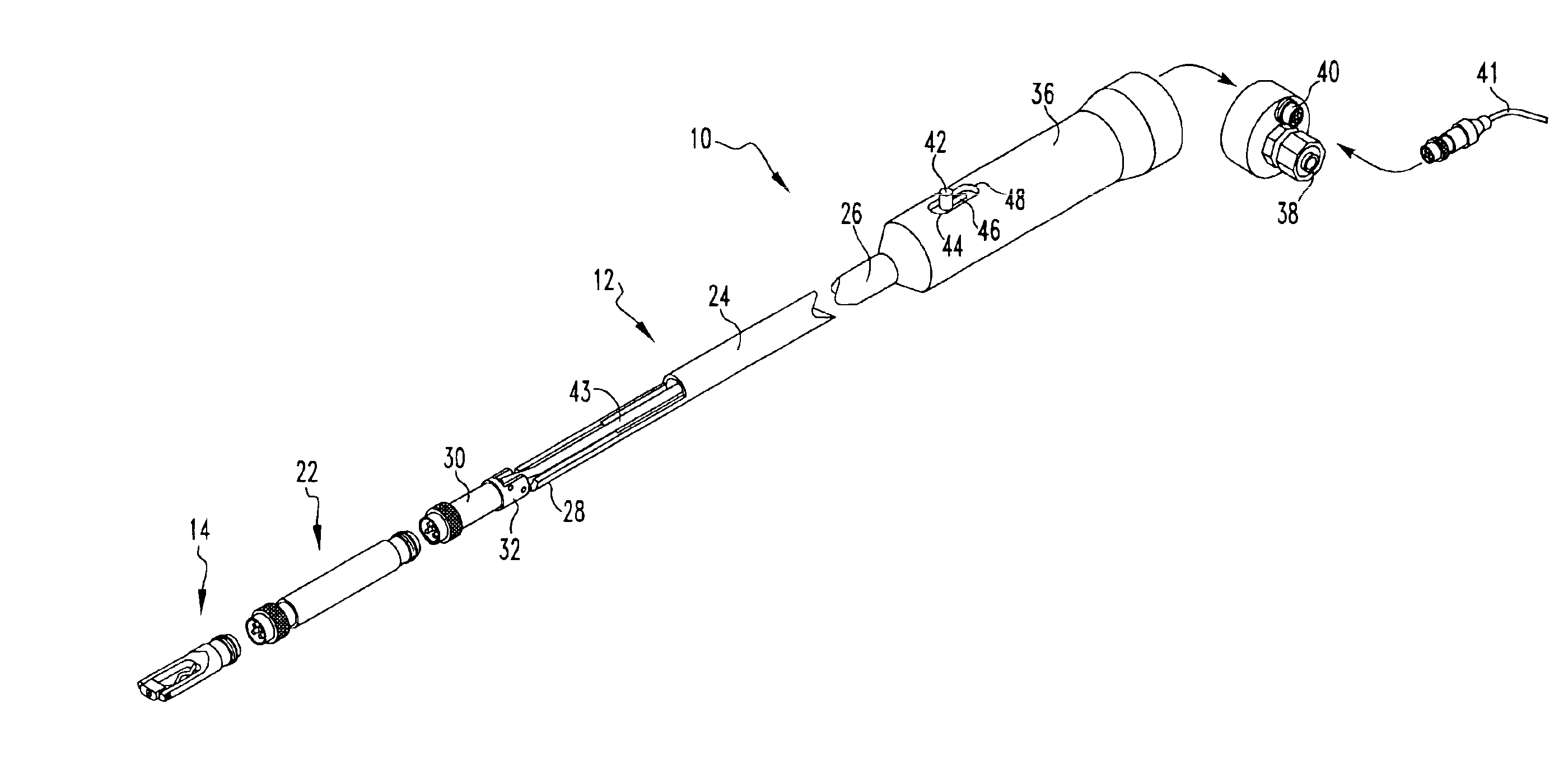
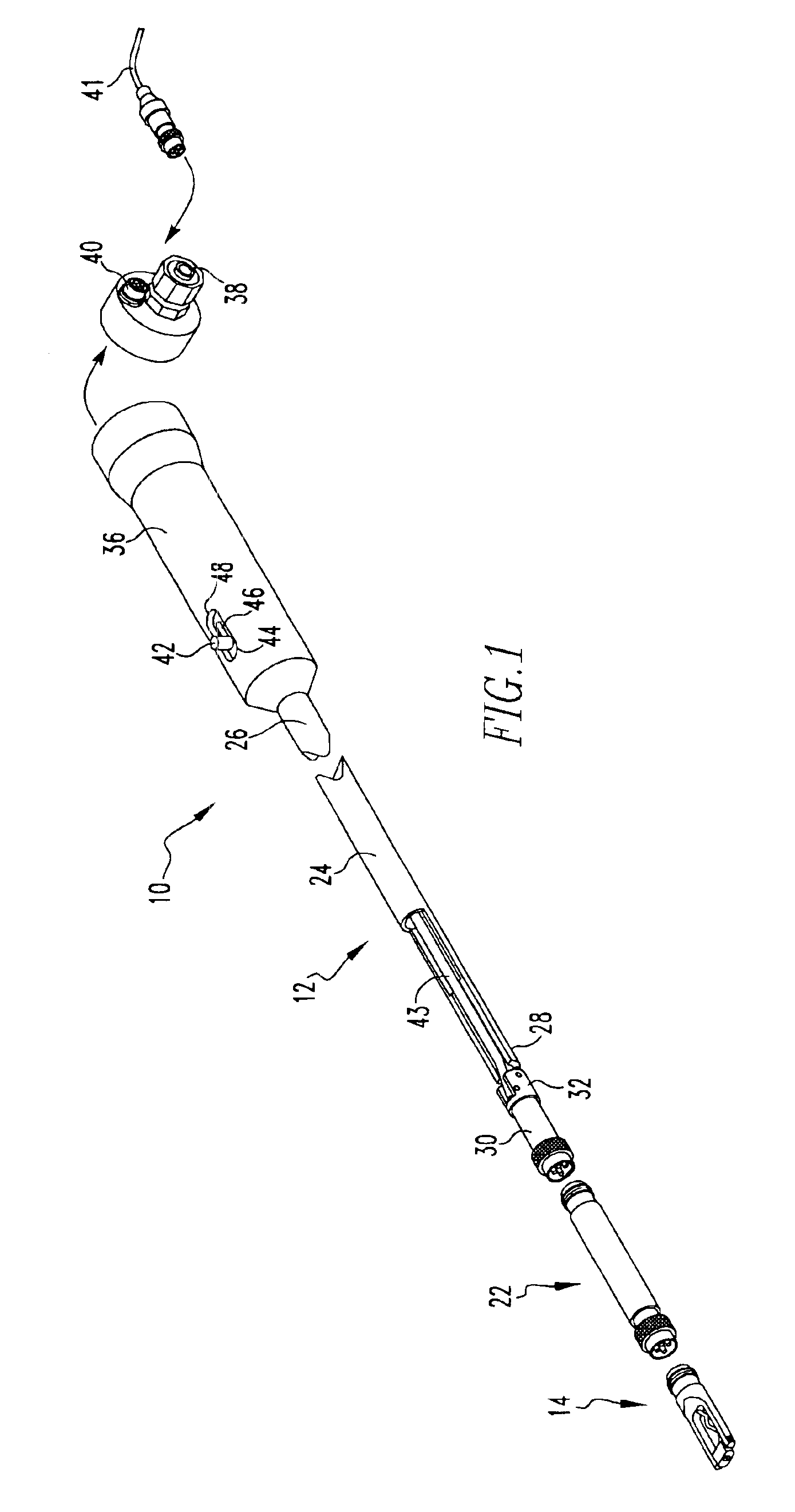
The present invention provides an improved eddy current inspection probe that is particularly suitable for accessing most or all blades within the turbine portion of a combustion turbine through an inspection port, without disassembly of the turbine.

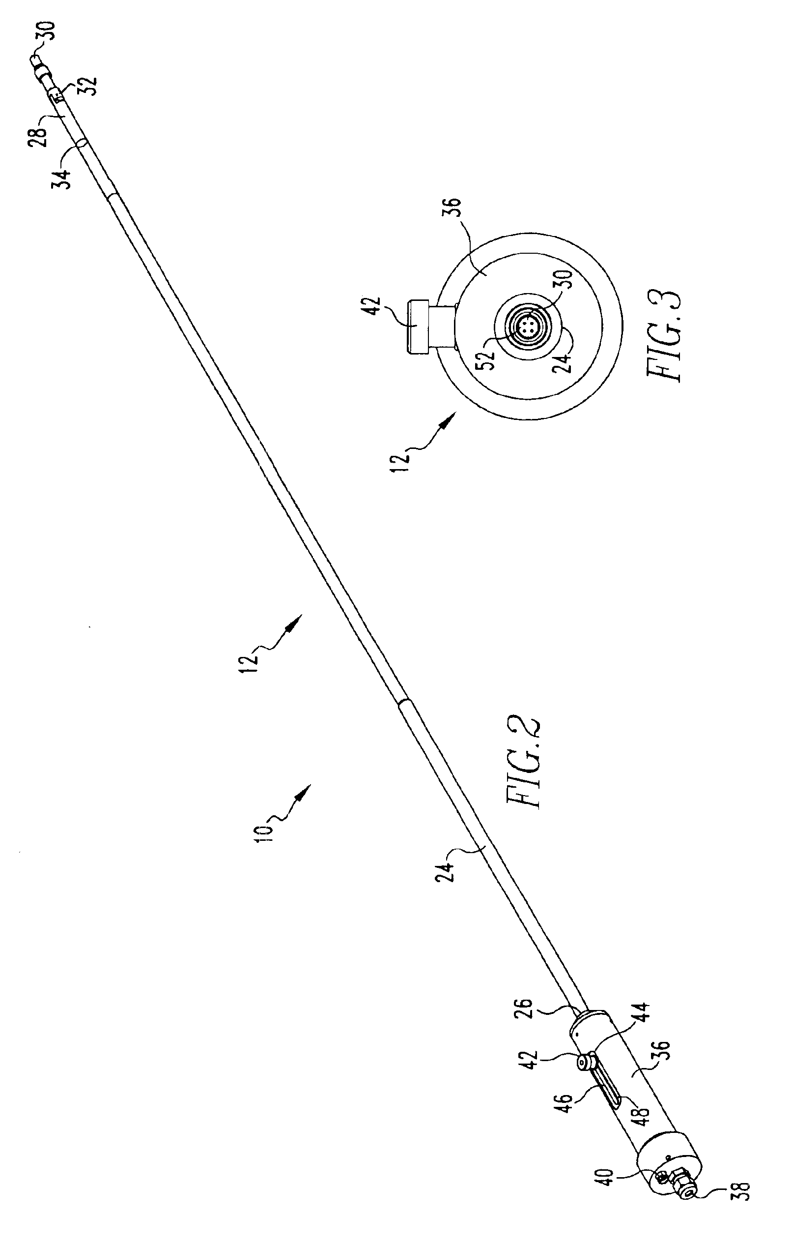
Referring to the drawings, the eddy current probe 10 includes a shaft 12, a bullnose tip 14 or groove nose tip 16, and also optionally includes a shaft extension 18, 20, or 22 therebetween.

Referring to FIGS. 1-3, the shaft 12 includes a main shaft body 24 having a handle end 26 and a probe end 28. The probe end 28 includes a tip connector 30, attached to the probe end 28 by the pivot 32. The tip connector 30 and other connectors described herein may be of the threaded collar type. The probe end 28 also preferably includes a video probe 34, located in close proximity to the pivot 32. The handle end 26 is rigidly secured to the handle 36. The handle 36 includes a video probe port 38 and an eddy current probe cable connector 40, providing f...


PUM

PropertyMeasurementUnit
eddy current probeaaaaaaaaaa
geometric surfacesaaaaaaaaaa
angleaaaaaaaaaa

Abstract

An eddy current inspection probe provides multiple interchangeable configurations for enabling an inspector to reach most or all portions of most or all turbine blades within a combustion turbine by inserting the probe through an inspection port, without disassembling the turbine. The probe shaft contains the electronic signal wire for the inspection tip and a port for a video probe, thereby facilitating use of the video probe and protecting these components. The inspection tip connector at the end of the main shaft is pivotally secured to the shaft, and may be set at any desired angle by using a semirigid or rigid member passing through the shaft, and connected to lever within the handle. Any one of a plurality of probe tips and shaft extensions may be selected to configure the inspection probe to reach a desired location within the turbine.

Description

BACKGROUND OF THE INVENTION1. Field of the InventionThe present invention provides an improved eddy current probe that is particularly useful for inspecting the interior of a combustion turbine without disassembly of the turbine.2. Description of the Related ArtEddy current testing of electrically conductive material is typically performed by exposing the material to an alternating magnetic field generated by a coil carrying an alternating current. The magnetic field generates small electric currents at or near the surface of the material, commonly known as eddy currents. The eddy currents generate their own magnetic fields, which, when they interact with the magnetic field of the exciting coil, will change the electrical impedance of the coil. The impedance of the exciting coil may be measured, and is compared with the impedance of a separate indicating coil, thereby detecting any condition that would affect the conductivity of the test material. Such conditions include cracks, voi...

Claims


Application Information

Patent Timeline
Patent Type & Authority Patents(United States)
IPC IPC(8): G01N27/90
CPCG01N27/902
Inventor HATCHER, CLIFFORDECHOLS, ROBERT
Owner SIEMENS ENERGY INC
Why Eureka
Try Eureka