Freight-loading system for an aircraft

Inactive Publication Date: 2005-03-15
TELAIR INTERNATIONAL GMBH
View PDF19 Cites 33 Cited by
  • Summary
  • Abstract
  • Description
  • Claims
  • Application Information

AI Technical Summary

Benefits of technology

It is an object of the present invention to provide a freight-loading system for a cargo hol

Problems solved by technology

The time taken for loading increases the costs to the operator of the cargo aircraft.
Hence e

Method used


Image

  • Freight-loading system for an aircraft
  • Freight-loading system for an aircraft
  • Freight-loading system for an aircraft

Examples


Embodiment Construction

In the following description, the same reference numerals are used for identical parts or parts with identical actions.

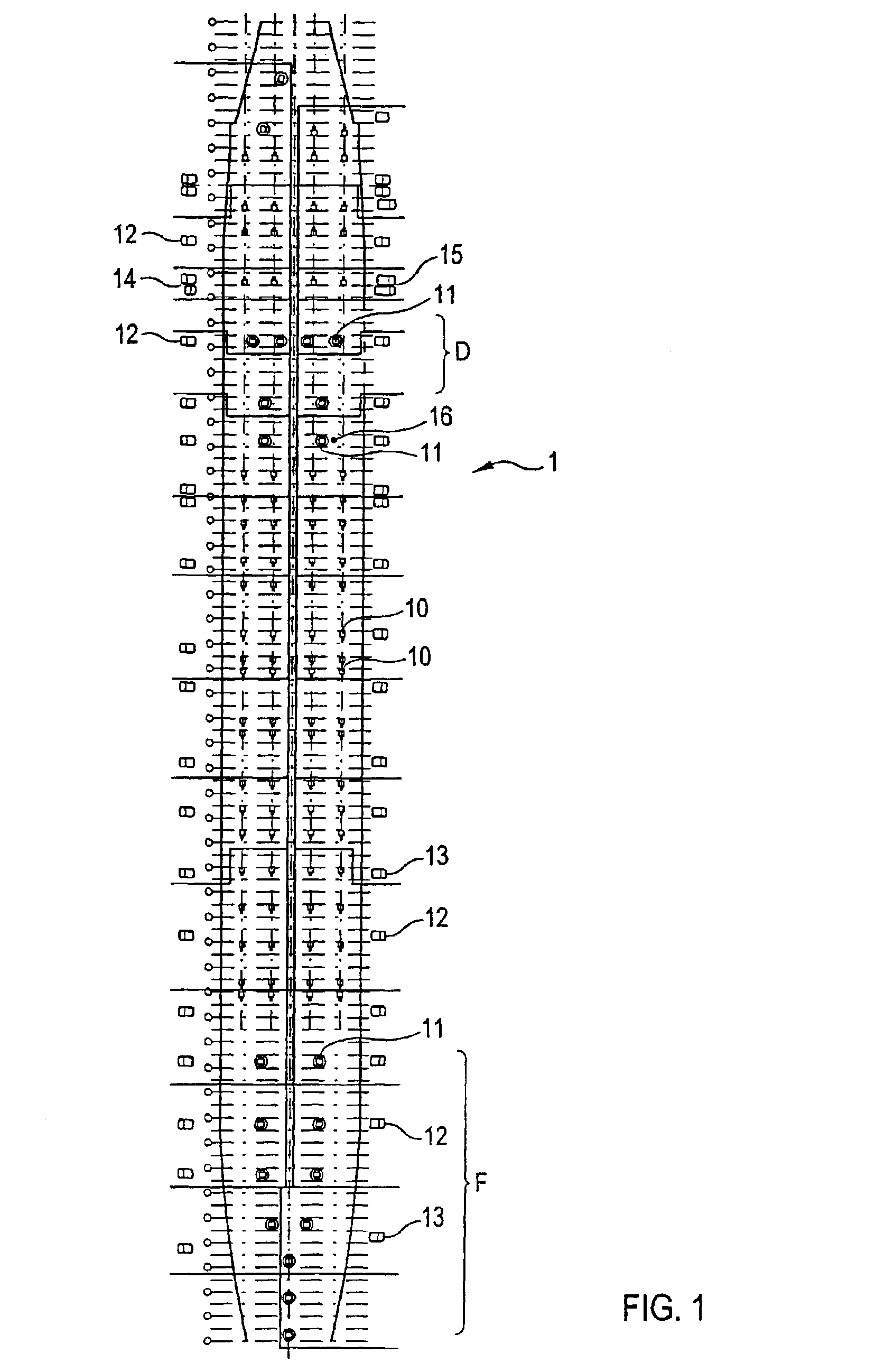
According to FIG. 1, in a cargo hold 1 of an aircraft a plurality of PDUs (power drive units) 10 are provided for the longitudinal transport of an item of freight that has been transported into the cargo hold, as well as other equipment in particular places, namely a door in region D and, disposed in the front region F, PDUs 11 that can be rotated about their vertical axis.

Along the side walls of the cargo hold are mounted control panels 12 to 14—shown schematically in FIG. 1—adjacent which are mounted the PDUs 10, 11 for the loading and unloading of PDUs. Hence the operating personnel can go along with the items of freight and continually check that they are correctly positioned.

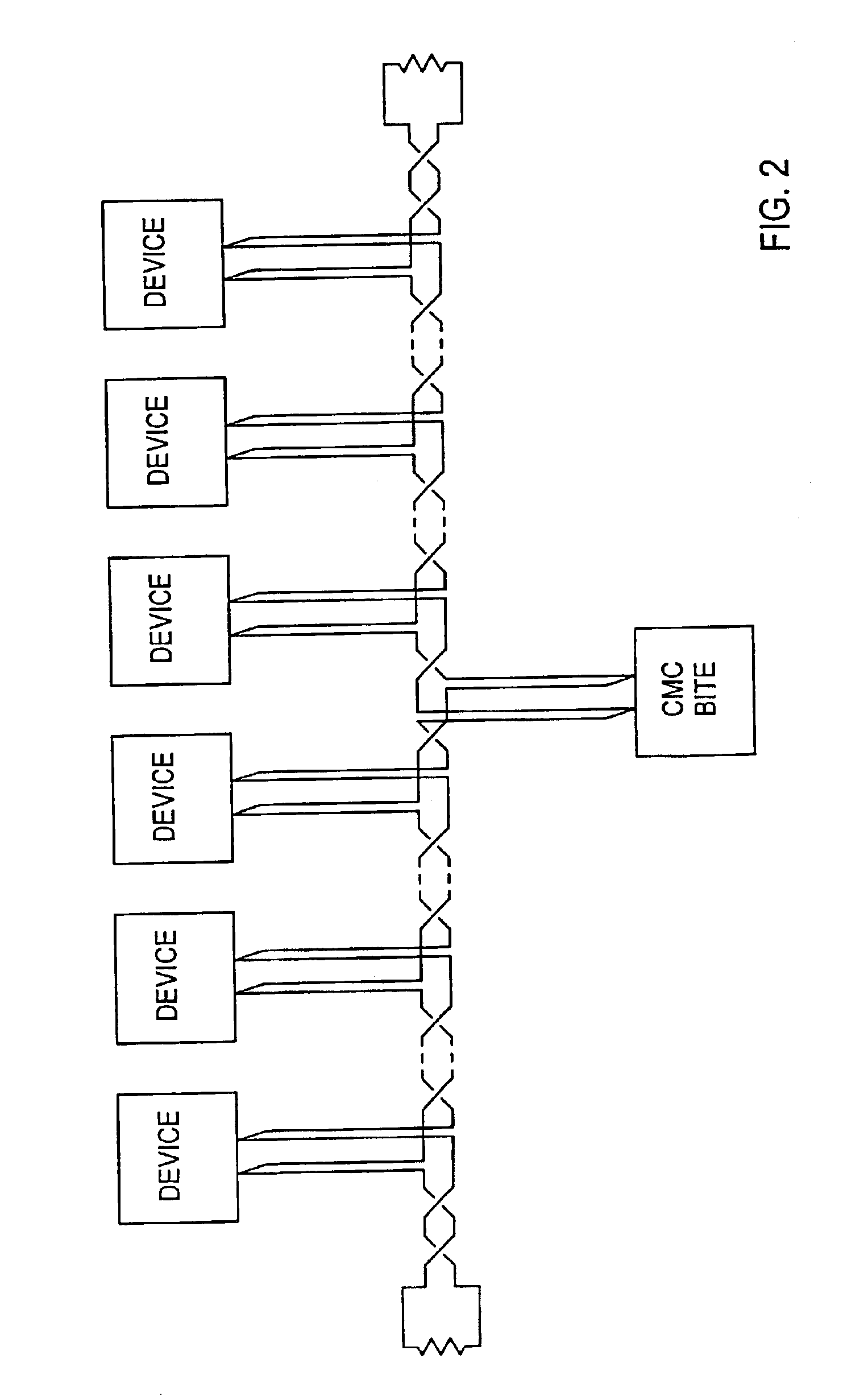
On the side wall behind the region D of the side door in the back of the cargo hold is disposed a CMC (control maintenance computer), which is connected to all the PDUs 10, 11 and panels 12...


PUM


Abstract

A freight-loading system in a cargo hold of an aircraft is provided that offers enhanced operating safety. The freight-loading system comprises a plurality of power drive units (PDUs), which can be actuated by control signals in such a way that items of freight can be maneuvered into or out of the cargo hold as well as within it. The power drive units (PDUs) are connected by control leads to control panels for actuation by personnel. A control maintenance computer (CMC) is provided and connected to the power drive units (PDUs) and the control panels, and is so designed that status information from the power drive units (PDUs) and the control panels can be read out, and that the power drive units (PDUs) and/or the control panels are controllable by the control maintenance computer (CMC).

Description

RELATED U.S. APPLICATIONSNot applicable.STATEMENT REGARDING FEDERALLY SPONSORED RESEARCH OR DEVELOPMENTNot applicable.REFERENCE TO MICROFICHE APPENDIXNot applicable.FIELD OF THE INVENTIONThe invention relates to a freight-loading system for use in a cargo hold of an aircraft and in particular to a system in which there are provided a plurality of PDUs (power drive units) with rollers on which, in response to appropriate control signals, items of freight are conveyed into and out of the cargo hold.BACKGROUND OF THE INVENTIONModern cargo aircraft, in particular of the type Boeing 747, have extraordinarily large cargo holds into which containers are loaded. The loading situations can vary widely. The items being stored in the hold are not only containers tailored exactly to the dimensions of the hold, which can be locked into position at prespecified places by means of elements provided there. Instead, it is also necessary to load items, the sizes of which require that they be conveyed...

Claims


Application Information

Patent Timeline
IPC IPC(8): B64C1/00B64C1/20B64D9/00
CPCB64C1/20G06Q50/30B64D9/00
Inventor HUBER, THOMASKIESER, BENEDIKTURCH, MATTHIASPERREITER, THOMASAUER, STEFAN
Owner TELAIR INTERNATIONAL GMBH
Why Eureka
Try Eureka