
Combining sidelobe canceller and mainlobe canceller for adaptive monopulse radar processing

a monopulse radar and mainlobe canceller technology, applied in direction finders, radio wave direction/deviation determination systems, antennas, etc., can solve the problems of preventing successful radar target detection and tracking, interception of more jamming, and wide beam width, so as to prevent an adverse interaction, suppress sidelobe jamming, and maintain the sensitivity of the monopulse ratio

Inactive Publication Date: 2005-03-15
LOCKHEED MARTIN CORP
View PDF5 Cites 35 Cited by
  • Summary
  • Abstract
  • Description
  • Claims
  • Application Information

AI Technical Summary

Benefits of technology

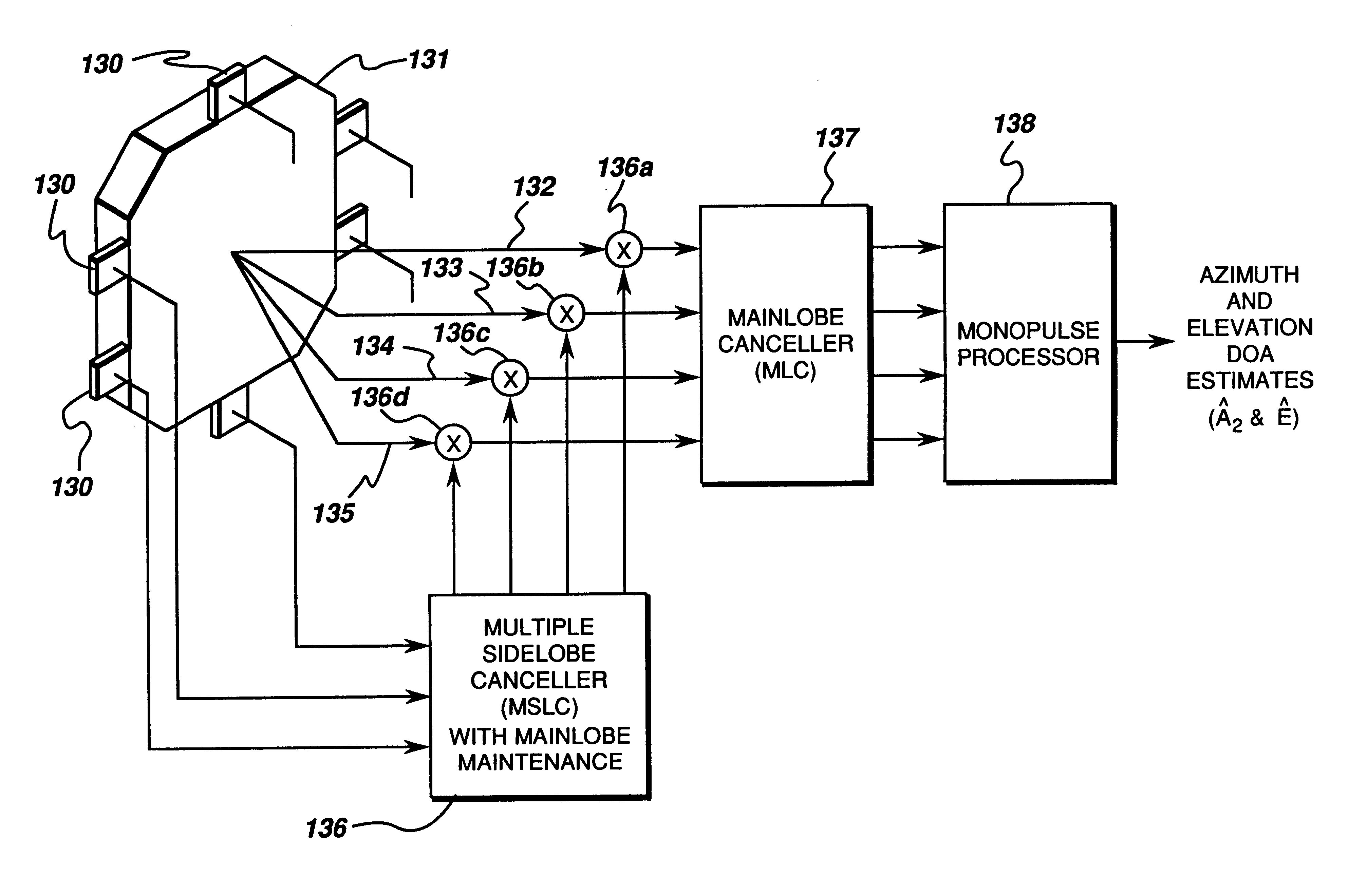
It is therefore an object of the invention to cancel both mainlobe and sidelobe jammers while maintaining target detection and angle estimation accuracy on mainlobe targets.
It is essential to include an appropriate mainlobe maintenance (MLM) technique in the first stage to prevent an adverse interaction between the two techniques. The MLM prevents the multiple sidelobe cancelling technique from interfering with the mainlobe cancellation technique.

Problems solved by technology

If not effectively countered, electronic jamming prevents successful radar target detection and tracking.
Large apertures to achieve small beamwidth results in interception of more jamming.
On the other hand, constrained apertures lead to wider beamwidth, which implies interception of more mainlobe jamming.
Heretofore, no viable or practical technique for cancelling simultaneous mainlobe and sidelobe jammers has been developed or fielded in a radar.
This makes the conception and development of such technique one of the more pressing and critical issues facing radar today.
The challenge is to develop adaptive beamforming architectures and signal processing algorithms to cancel mainlobe and sidelobe jammers while maintaining target detection and angle estimation accuracy on mainlobe targets.
Third, as a consequence of using the arrays simultaneously, Clark's approach does not include mainlobe maintenance, thereby introducing distortion into the main beam.

Method used


Image

  • Combining sidelobe canceller and mainlobe canceller for adaptive monopulse radar processing
  • Combining sidelobe canceller and mainlobe canceller for adaptive monopulse radar processing
  • Combining sidelobe canceller and mainlobe canceller for adaptive monopulse radar processing

Examples


Embodiment Construction

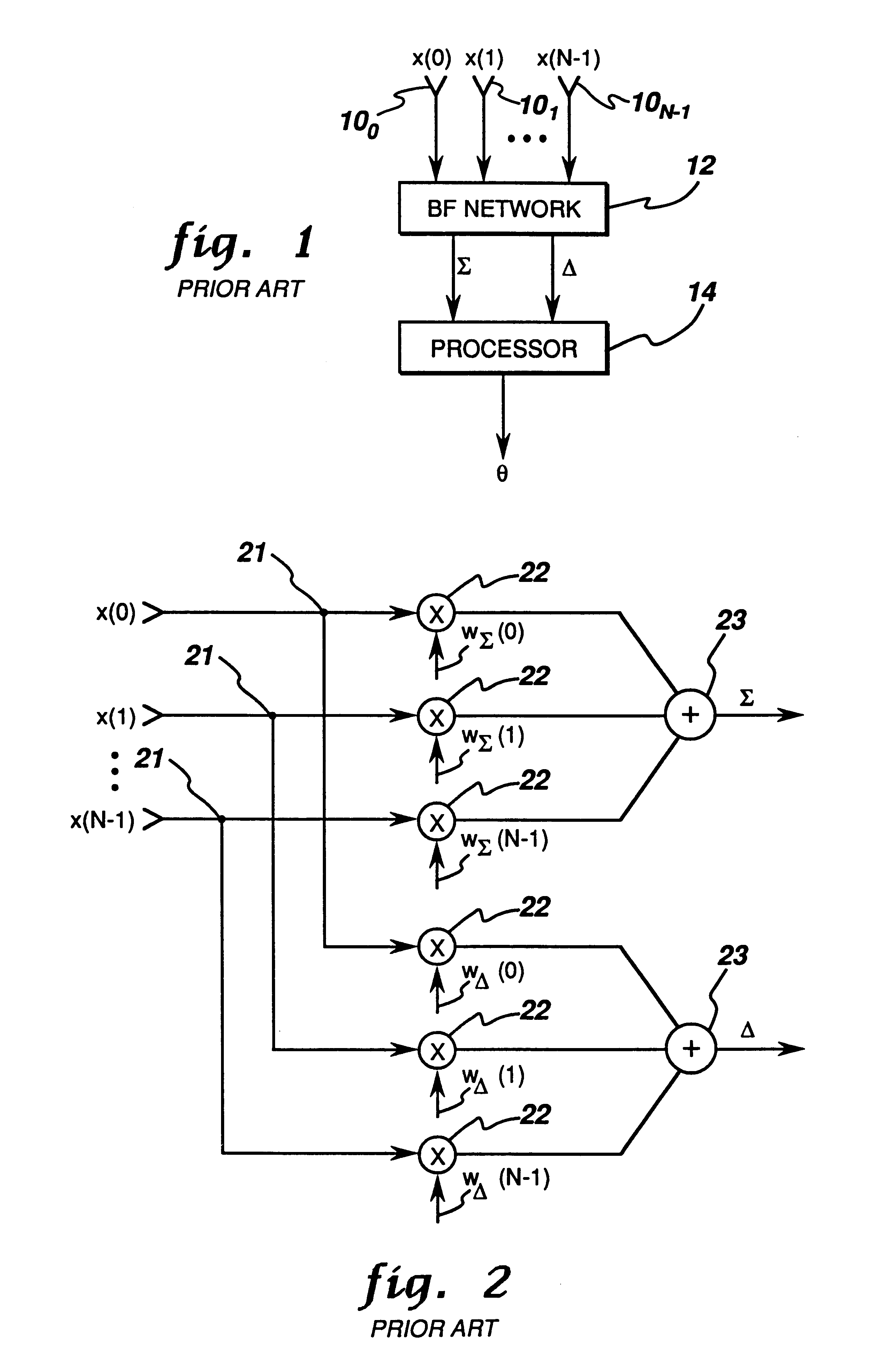
A monopulse technique for DOA estimation is implemented for a linear array of antenna elements 100 to 10N−1 which provide respective signals x(0), . . . , x(N−1), shown in FIG. 1, to the beamforming (BF) network 12 for combining the input signals from the elemental receiver. The output signals of BF network 12 are the sum Σ and difference Δ signals which are processed in a processor 14 to generate an output signal θ representing the direction of arrival estimation.

Beamforming network 12 is more fully illustrated in FIG. 2 and comprises voltage splitters 21, weighting networks 22 and adders 23. Each of the N input signals is split into two paths which are linearly weighted, and in each of the two paths the N signals are added together.

The sum Σ and difference Δ signals are given by equations (1) and (2) as Σ⁢ =WΣH⁢x_(1)Δ=WΔH⁢x_(2)

respectively. When there is no jamming, Taylor and Bayliss weightings are typically used for sum beams and difference beams, respectively, so as to have a n...


PUM


Abstract

An improvement in monopulse radar achieves nulling of a single mainlobe jammer and multiple sidelobe jammers while maintaining the angle measurement accuracy of the monopulse ratio by cascading a multiple sidelobe canceller and a mainlobe canceller, and imposing a mainlobe maintenance technique during the sidelobe jammer cancellation process so that the results of the sidelobe jammer cancellation process do not distort the subsequent mainlobe cancellation process. In this manner, the sidelobe jammers and the mainlobe jammer are cancelled sequentially in separate processes.

Description

BACKGROUND OF THE INVENTIONThis invention generally relates to radar techniques for determining angular location of a target and, more particularly, to an improvement in the monopulse technique so as to maintain accuracy of the monopulse ratio in the presence of simultaneous jamming from multiple sidelobe jammers and a single mainlobe jammer.The monopulse technique is a radar technique in which the angular location of a target can be determined within fractions of a beamwidth by comparing measurements received by two or more simultaneous beams. This technique for direction of arrival (DOA) estimation of a target is widely employed in modern surveillance and tracking radar. See, for example, D. K. Barton, “Modern Radar Systems Analysis,”Artech House (1988), M. Sherman, “Monopulse Principles and Techniques,”Artech House (1988), and I. Leanov and K. I. Fomichev, “Monopulse Radar,”Artech House (1986). In a typical phased array or digital beamforming (DBF) radar, one beam is formed in tr...

Claims


Application Information

Patent Timeline
Patent Type & Authority Patents(United States)
IPC IPC(8): G01S13/36G01S13/00G01S7/36
CPCG01S7/2813G01S7/36H01Q25/02H01Q3/2611H01Q3/30G01S13/44
Inventor YU, KAI-BORMURROW, DAVID JAY
Owner LOCKHEED MARTIN CORP
Learn More