Control system, display device, control-use host computer, and data transmission method

a display device and control system technology, applied in the direction of programme control, electric controllers, total factory control, etc., can solve the problems of excessive data communication time, inconvenient transmission of enormous data such as character and image data, and excessive connection change, so as to save time and labor in incorporating a control

Inactive Publication Date: 2005-03-15
SCHNEIDER ELECTRIC JAPAN HLDG LTD
View PDF32 Cites 29 Cited by
  • Summary
  • Abstract
  • Description
  • Claims
  • Application Information

AI Technical Summary

Benefits of technology

Aspects of the present invention have been made based on this finding, and an object of the present invention is to provide a control system in which a display device that conventionally was used exclusively for display of a control state is placed at a center of data communication. This ensures that a control unit such as a PLC can be exclusively used for I / O control whereby a load on the control unit is decreased. At the same time, it ensures that innumerable communication protocols of control units need not be considered on the side of a data processing device of the host computer or the like or on the display device side, whereby software operations are reduced.
According to the foregoing arrangement, taking advantage that each control unit is connected with the host device via the display device that has a high computing competence and high applicability to data communication, the display device provides protocol conversion. In so doing, the control unit is allowed to use an arbitrary protocol that differs depending on the manufacturer or the product, while the network is made to use the predetermined common protocol, and consequently, extension or change of the control system easily executed.

Problems solved by technology

However, developed from a sequencer utilizing a relay, a PLC best performs in operations related with input / output control, such as an ON / OFF control of a switch and an operation of taking in data from a sensor, and use of a PLC as a center of data communication will overload the PLC, even though such use is possible.
Furthermore, data communication time becomes excessively long, for instance, upon an initial setting before control when more data transmission is required, as compared with during control.
In a case where a personal computer is directly connected to a display device of a PLC to shorten the data communication time, connection change becomes extremely bothersome.
Therefore, they are capable of transmitting data like data expressing control states of the apparatuses to be controlled to the display devices 502α, 502β, and 502γ, but they are not suitable for transmission of enormous data such as character and image data.
Therefore, the operation of changing the screen display is complicated, and it is necessary to consecutively connect the personal computer 506 with the display device whose screen display is to be changed, one after another, for downloading.
Therefore, there arises a problem that an offline time is prolonged.
Thus, there exists a problem of extreme inconvenience.

Method used


Image

  • Control system, display device, control-use host computer, and data transmission method
  • Control system, display device, control-use host computer, and data transmission method
  • Control system, display device, control-use host computer, and data transmission method

Examples


Embodiment Construction

The following description will explain the aspects of the present invention, referring to examples of the present invention and comparative examples. Note that however the aspects of the present invention are not limited by the examples at all.

[First Aspect]

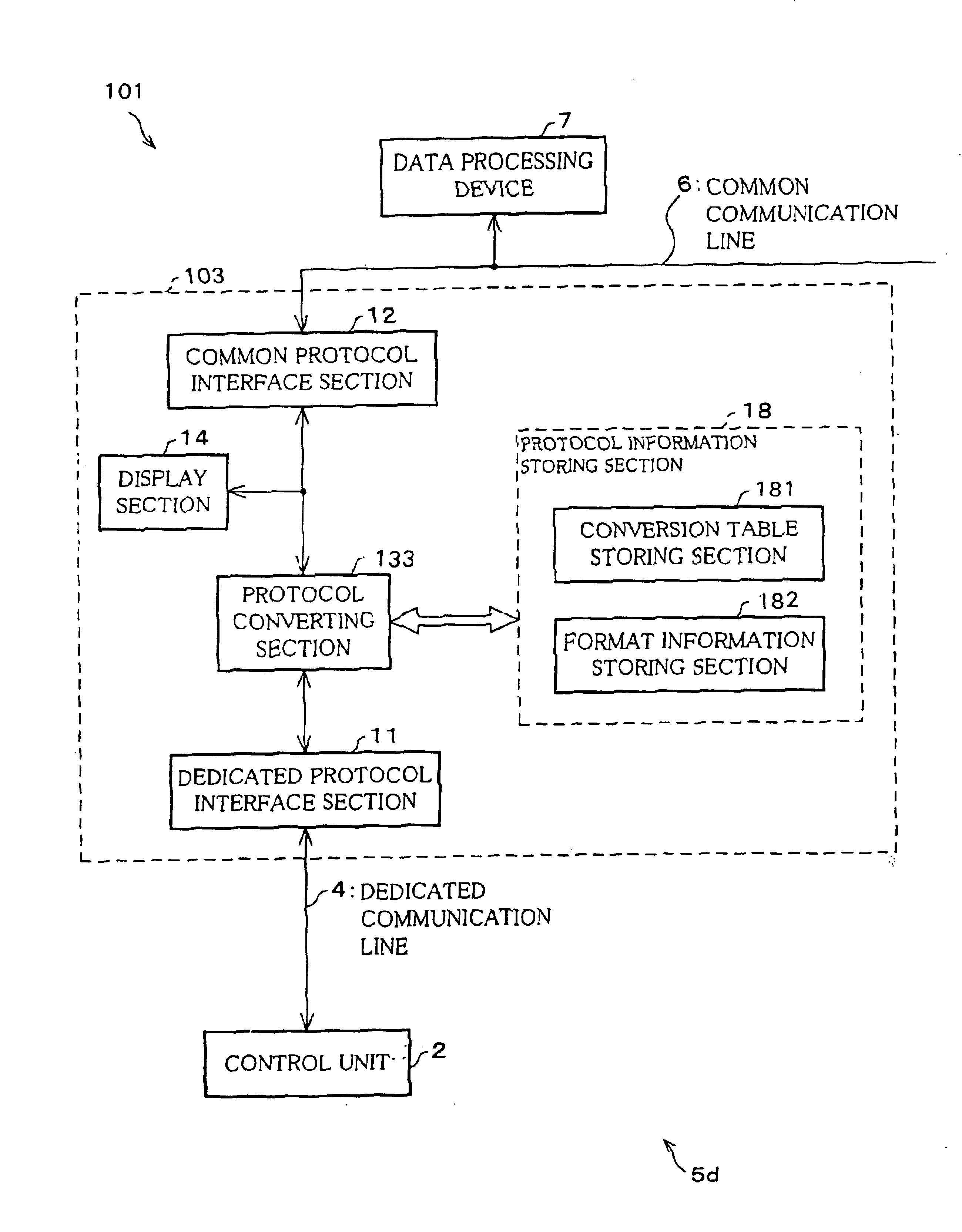
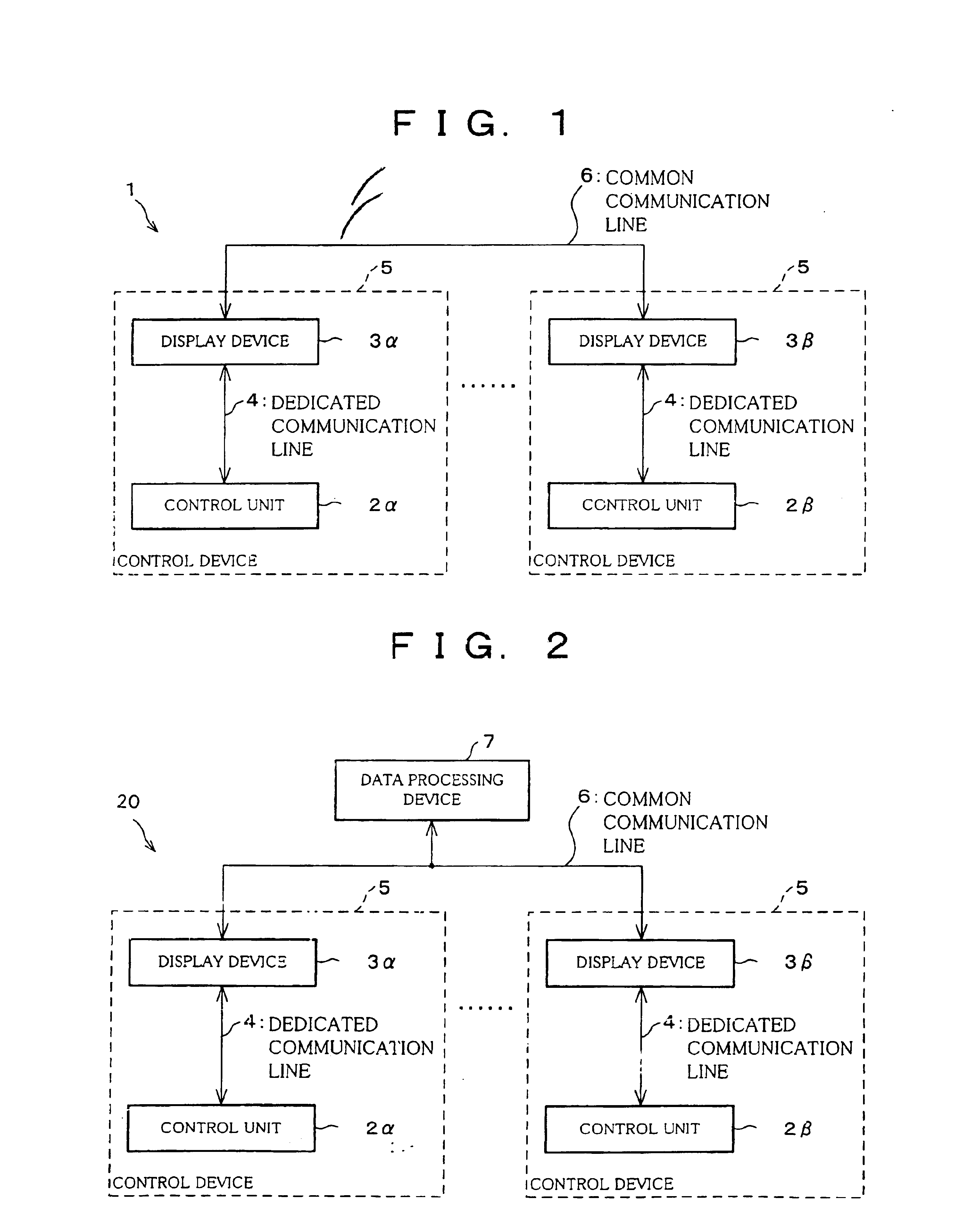
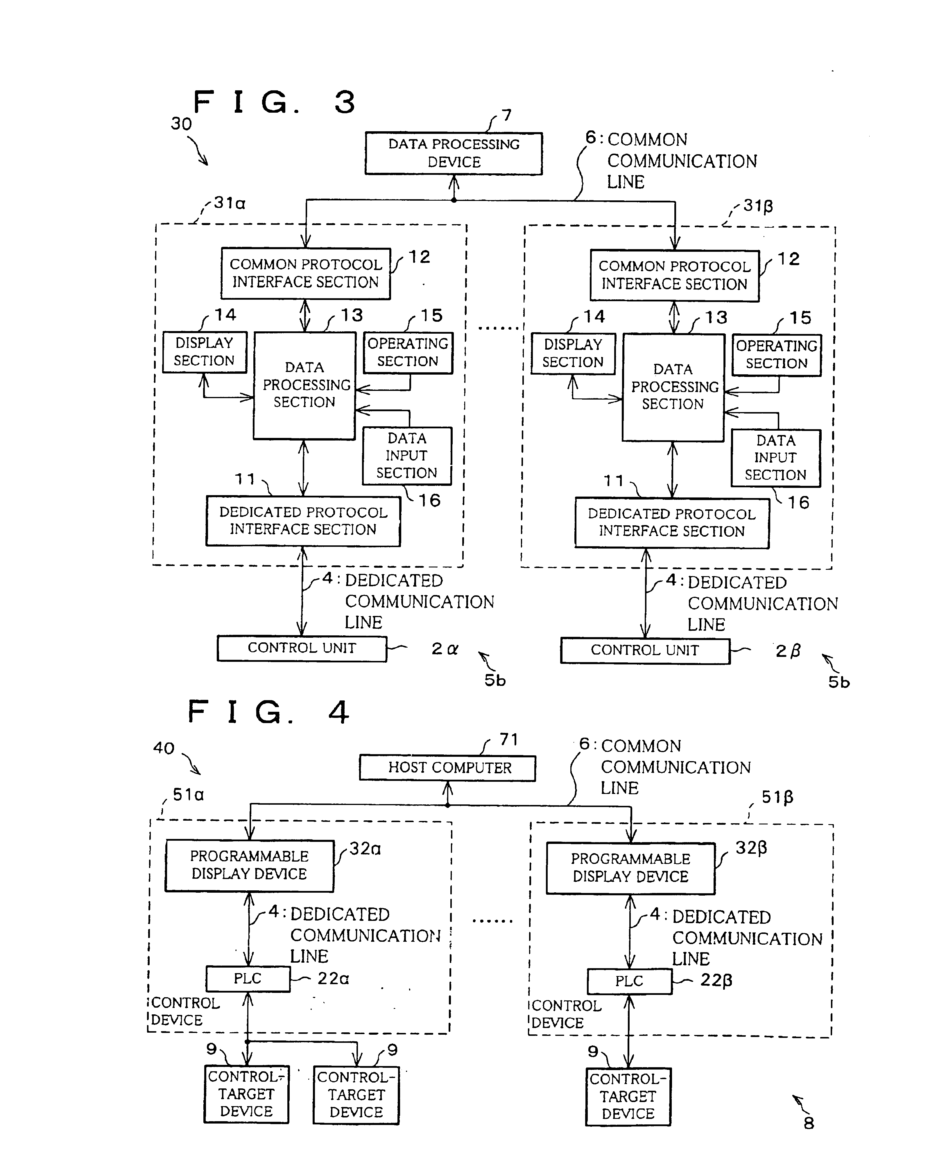
The following description will explain an aspect of the present invention while referring to FIG. 1. As shown in FIG. 1 that schematically illustrates an overall structure of a control system 1 in accordance with the aspect of the present invention, the control system 1 is provided with a plurality of control devices 5 each of which includes a control unit 2α, 2β, a display device 3α, 3β capable of display suitable to a controlled state of the control unit 2α, 2β and a dedicated communication line 4 for connection between the control unit 2α, 2β and the display device 3α, 3β so that data can be transferred between the control devices 5. In each control device 5, the control unit 2α, 2β and the display device 3α, 3β execute data c...


PUM


Abstract

A control system including control devices with each control device including a control unit and a display device connected with the control unit via a dedicated communication line and being capable of display corresponding to a control state of the control unit. The display device includes a communication port connected with a control unit and a communication port connected with a data processing device, and a data processing section. Further, the data transmission method includes a dedicated protocol communication transmitting data with a processing device and a common protocol communication transmitting data with another processing device. In addition, the control-host computer used in the control system includes a control unit controlling a control target and a display device.

Description

TECHNICAL FIELDThe present invention relates to (i) a control system that has a plurality of control devices each of which includes a method of control e.g., control unit such as a programmable logic controller (hereinafter referred to as PLC) and a display device displaying a control state of the method of control, and that enables transmission between the control means, (ii) a display device for the control system, (iii) a control-use host computer suitably used in a control system, and (iv) a data transmission method regarding data transmission between a first data processing device having its own communication protocol specialized for itself like the foregoing control unit and a second data processing device having a common communication protocol like a personal-computer-applied device.BACKGROUND OF THE INVENTIONIn a conventional control system, generally, a PLC is placed at the center of control, and a plurality of PLCs and host computers are connected via predetermined interfa...

Claims


Application Information

Patent Timeline
Patent Type & Authority Patents(United States)
IPC IPC(8): G05B19/048G05B15/00G05B11/01G05B19/05G05B23/02G05B9/03G06F13/00G09G5/00H04L12/66G05B19/042G05B19/418G06F15/16
CPCG05B19/0421G05B19/052G05B19/4185G05B2219/31369G05B2219/31087G05B2219/31088G05B2219/31227G05B2219/25012Y02P90/02G06F13/00
Inventor II, NOBUHIROYOSHIDA, MINORUMORIGAKI, YUICHIKATO, SATOSHISHINOHARA, AKIO
Owner SCHNEIDER ELECTRIC JAPAN HLDG LTD
Why Eureka
Try Eureka