
Integrated diagnostic for photoelastic modulator

a technology of optical diagnostic system and photoelastic modulator, which is applied in the direction of optical radiation measurement, interferometric spectrometry, instruments, etc., can solve the problems of undesirable situation and low operating frequency

Inactive Publication Date: 2005-03-15
HINDS INSTR
View PDF8 Cites 14 Cited by
  • Summary
  • Abstract
  • Description
  • Claims
  • Application Information

AI Technical Summary

Benefits of technology

In view of the foregoing, one can appreciate the value of real-time information indicating the actual performance of the PEM (that is, the particulars of the retardance characteristics induced by the PEM into the light that passes through it). Moreover, this information may be used as feedback control of the PEM to more accurately control the PEM operation.

Problems solved by technology

This results in an operating frequency that drifts with ambient temperature, as well as during warm-up and after changes in the set retardation amplitude.
Such a situation may be undesirable in certain applications where the PEM's operating frequency, as well as its amplitude, must be kept constant.

Method used


Image

  • Integrated diagnostic for photoelastic modulator
  • Integrated diagnostic for photoelastic modulator

Examples


Embodiment Construction

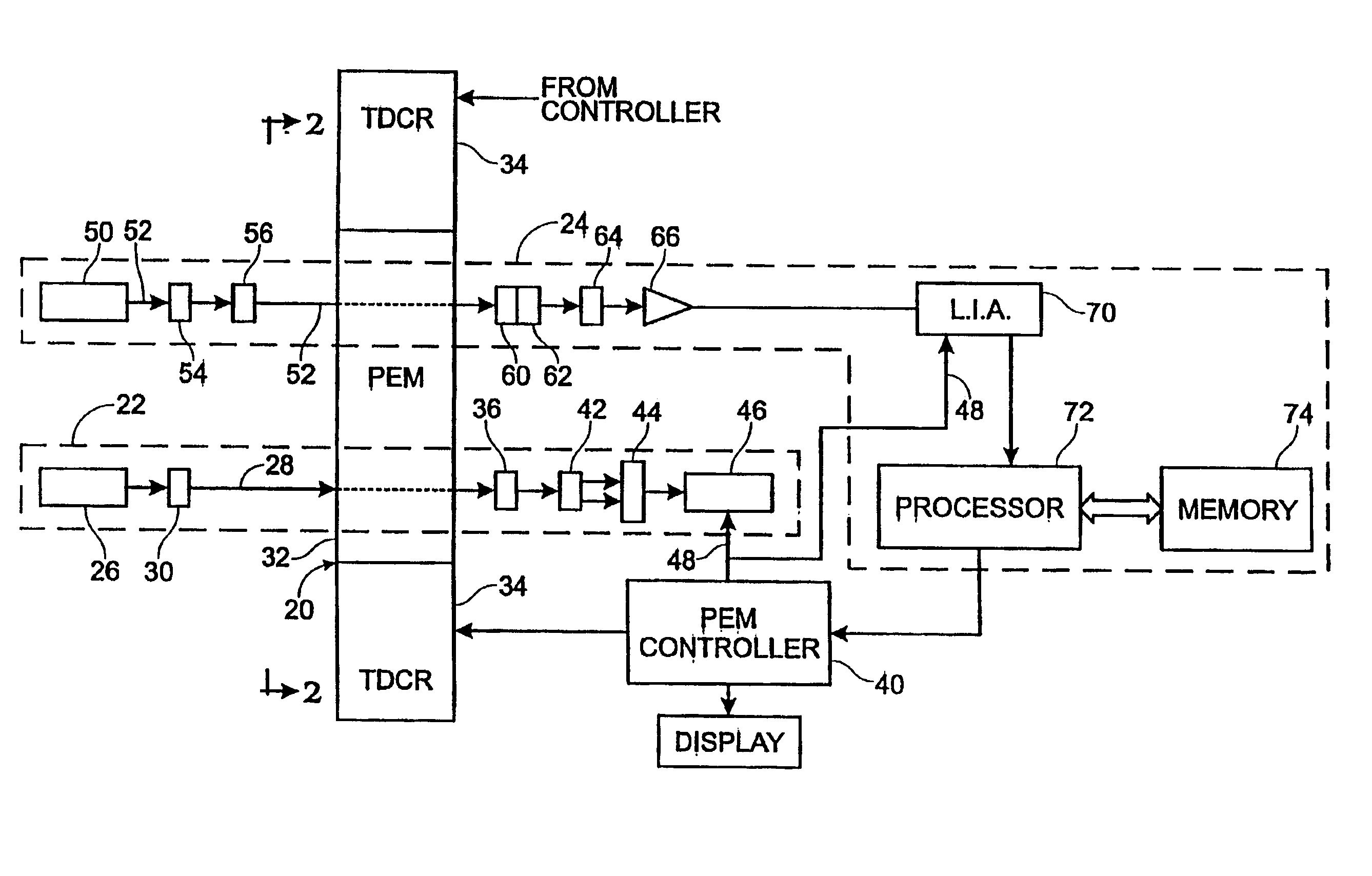
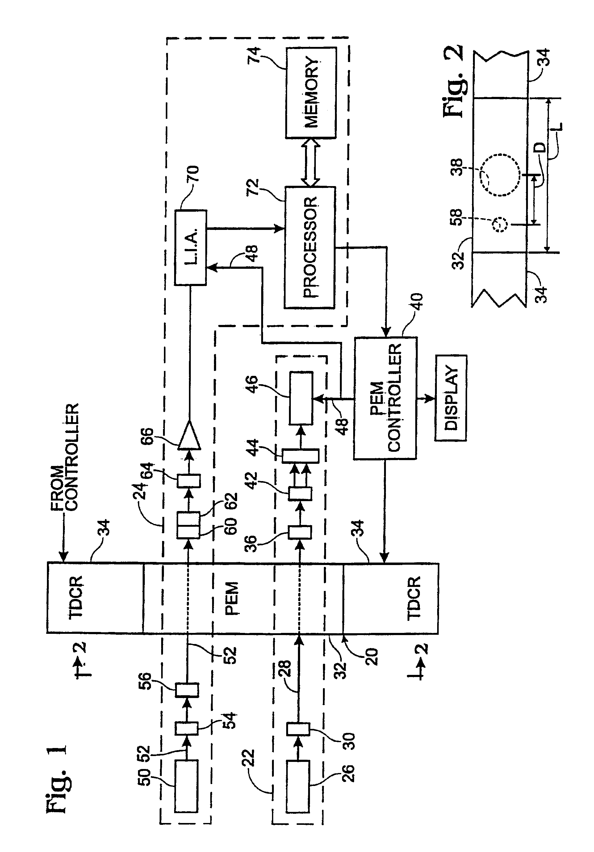
The diagram of FIG. 1 depicts a photoelastic modulator (PEM) 20 that is used in a primary optical setup 22 (described more below) and that has integrated with it a diagnostic system 24 configured in accordance with present invention.

Primary Optical Setup

The block 22 shown in dashed lines in FIG. 1 is intended to represent any of a variety of optical setups with which a PEM may be employed. One such setup is described in international application number PCT / US99 / 03481, hereby incorporated by reference (the '481 application).

The setup employed in the '481 application is used for precise measure of the birefringence characteristics of an optical sample. That setup is summarized next for the purposes of explaining an exemplary, primary setup 22 with which the later-described diagnostic system may be integrated.

The primary setup 22 includes a primary light source 26 such as a HeNe laser that has a wavelength of 632.8 nanometers (nm). The light beam 28 emanating from the source has a cros...


PUM

PropertyMeasurementUnit
frequencyaaaaaaaaaa
wavelengthaaaaaaaaaa
spot sizeaaaaaaaaaa

Abstract

A diagnostic system (24) for a PEM (20) provides optically determined information about the retardance characteristics induced by the PEM (20). The diagnostic system (24) is integrated with the PEM (20) so that the PEM (20) performance may be diagnosed or monitored during operation of the PEM (20). Specifically, the diagnostic system (24) is used alongside an optical setup (22) that employs a primary light beam (28) for conventional purposes such as polarimetry, optical metrology, etc. The diagnostic system (24) includes its own diagnostic light source (50) that is directed through the optical element (32) of the PEM (20) at a location remote from the primary aperture (38) of the PEM (20). Thus, the diagnostic system (24) and the primary PEM (20) operation can be undertaken simultaneously, with one not interfering with the other. The output of the diagnostic system reflects the actual retardance characteristic provided by the PEM (20) and can be used as feedback to adjust the PEM control as needed.

Description

TECHNICAL FIELDThis application relates to an integrated optical diagnostic system for a photoelastic modulator.BACKGROUND AND SUMMARY OF THE INVENTIONA resonant photoelastic modulator (PEM) is an instrument that is used for modulating the polarization of a beam of light. A PEM employs the photoelastic effect as a principle of operation. The term “photoelastic effect” means that an optical element that is mechanically strained (deformed) exhibits birefringence that is proportional to the amount of strain induced into the element. Birefringence means that the refractive index of the element is different for different components of polarized light.A PEM includes an optical element, such as fused silica, that has attached to it a piezoelectric transducer for vibrating the optical element at a fixed frequency, within, for example, the low-frequency, ultrasound range of about 20 kHz to 100 kHz. The mass of the element is compressed and extended as a result of the vibration.The compressio...

Claims


Application Information

Patent Timeline
Patent Type & Authority Patents(United States)
IPC IPC(8): G01B9/02G02F1/03G01J3/45G01J4/00G02F1/01
CPCG02F1/0131G02F1/0123
Inventor KADLEC, PAUL
Owner HINDS INSTR
Learn More