Power on reset circuit for a microcontroller

a microcontroller and power on reset technology, applied in the field of microcontrollers, can solve the problems of affecting the operation of certain microcontroller functions, affecting the stability of power state,

Inactive Publication Date: 2005-03-15
MONTEREY RES LLC
View PDF7 Cites 105 Cited by
  • Summary
  • Abstract
  • Description
  • Claims
  • Application Information

AI Technical Summary

Benefits of technology

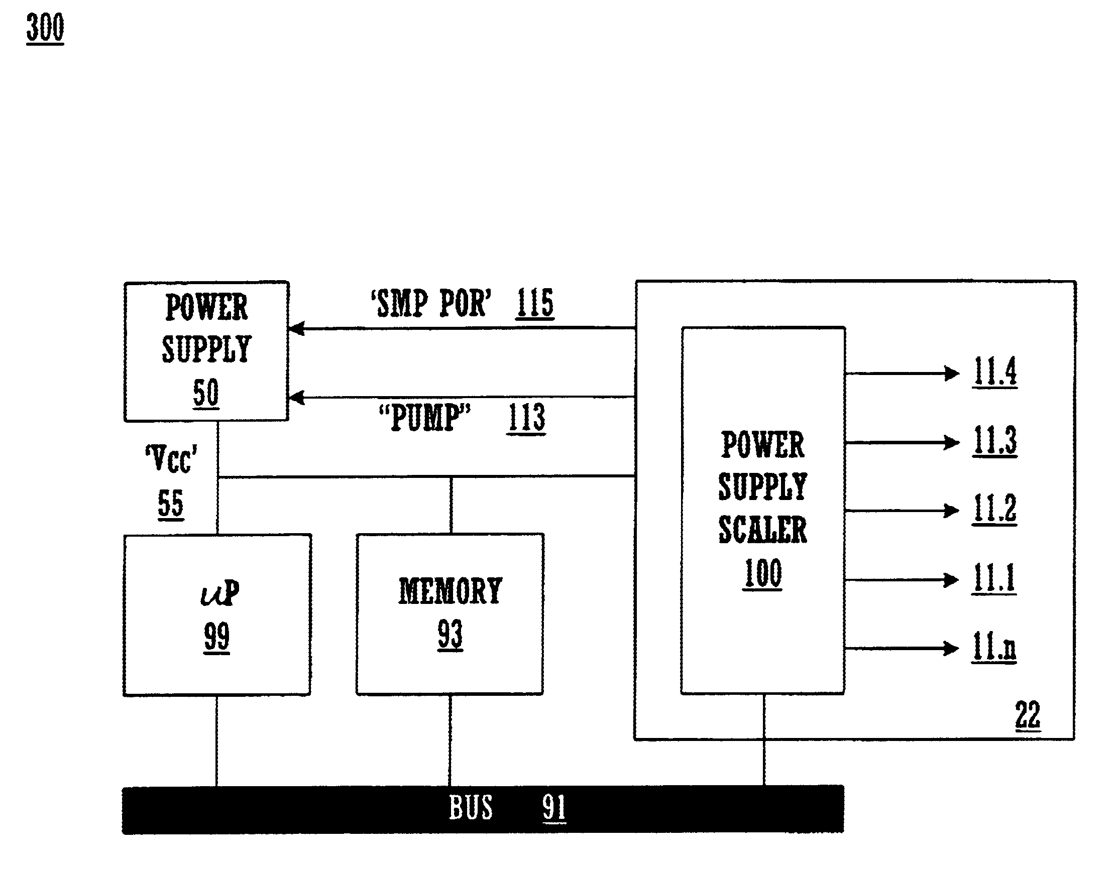
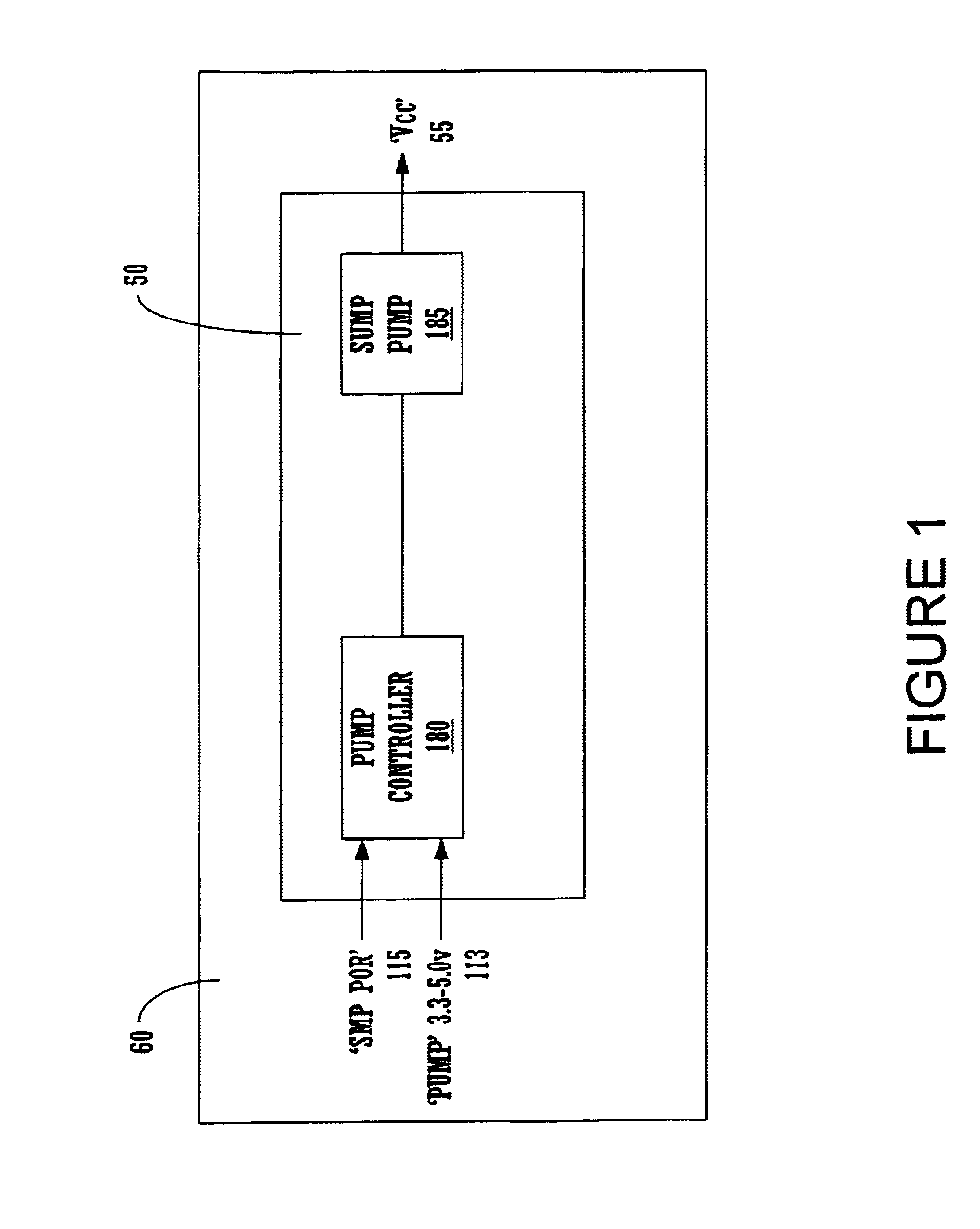
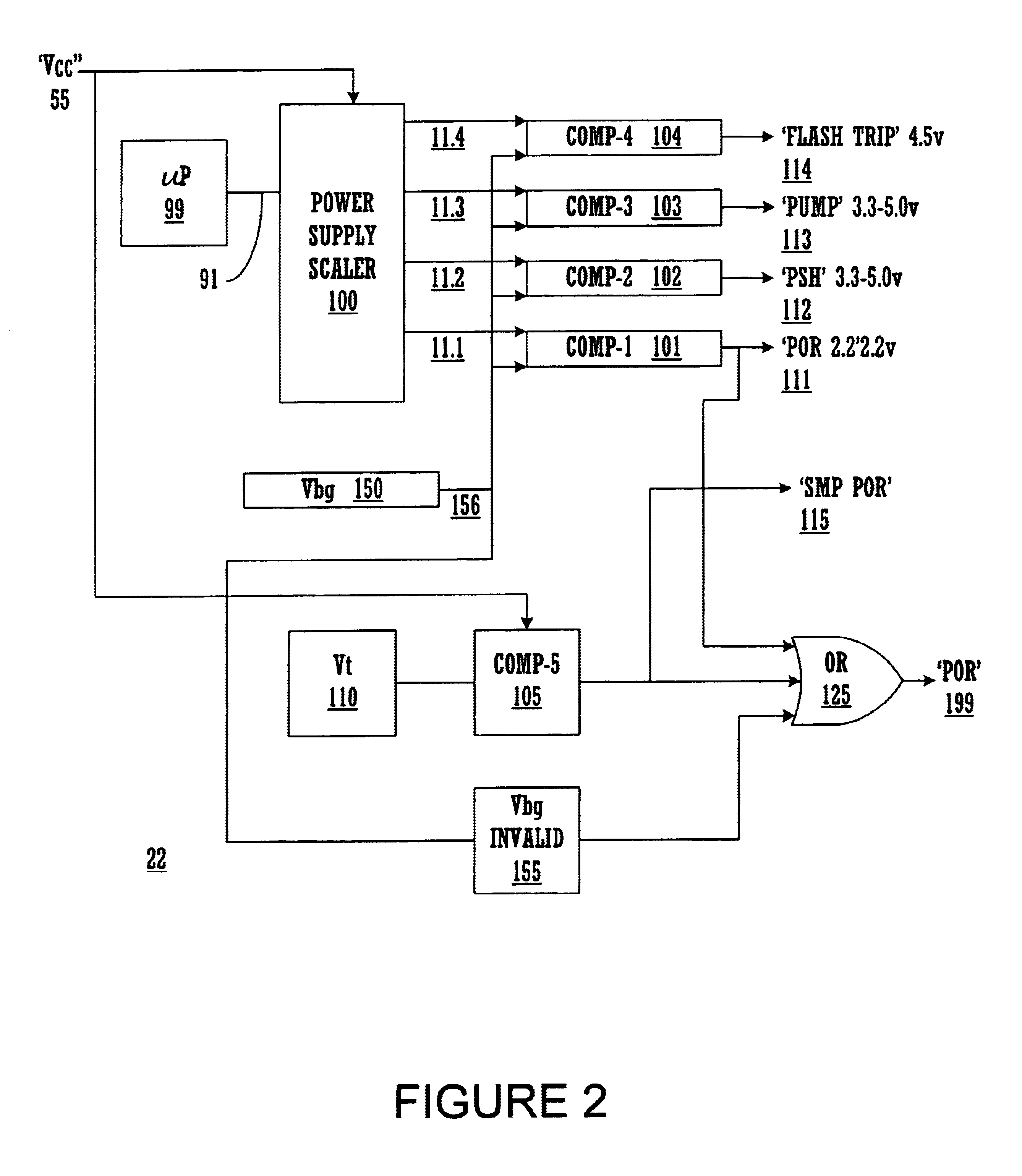
The present invention provides a robust circuit and system which effectively functions to provide power on reset (POR) capabilities for a microcontroller, at more than a single level, as well as post-boot-up power stability functions. The present invention also provides a circuit and system that utilizes the resources of installed POR circuitry to additionally control a microcontroller's switch mode pump (SMP), both during boot-up and

Problems solved by technology

However, several other microcontroller functions related to power state stability either go unaddressed, or require separate functionalities to enable them.
Further, certain microcontroller operational functions may be disrupted by power system instability.
A microcontroller's output may be corrupted and data lost due to power instability during routine (e.g., post-startup) operation.
Microcontroller output corruption is problematic, especially in critical instrumentation and control applications.
In certain critical applications, variation in a microcontroller's output due to power instability can have deleterious consequences.
Among its other functionalities, flash memory is one microcontroller system in particular, which is vulnerable to power system instability.
The conventional art is problematic because it either fails to address microcontroller power stability issues beyond initial boot-up POR, requires the dedication of existing system resources to address them, or requires the provision of additional resources to address them.
In the first instance, power stability problems remain unsolved.
In the second two instances, the solutions are expensive.
Further, these effectively internal control fu

Method used


Image

  • Power on reset circuit for a microcontroller
  • Power on reset circuit for a microcontroller
  • Power on reset circuit for a microcontroller

Examples


Embodiment Construction

Reference will now be made in detail to the preferred embodiments of the invention, examples of which are illustrated in the accompanying drawings. While the invention will be described in conjunction with the preferred embodiments, it will be understood that they are not intended to limit the invention to these embodiments. On the contrary, the invention is intended to cover alternatives, modifications and equivalents, which may be included within the spirit and scope of the invention as defined by the appended claims. Furthermore, in the following detailed description of the present invention, numerous specific details are set forth in order to provide a thorough understanding of the present invention. However, it will be obvious to one of ordinary skill in the art that the present invention may be practiced without these specific details. In other instances, well-known methods, procedures, components, and circuits have not been described in detail so as not to unnecessarily obscu...


PUM


Abstract

In accordance with one embodiment of the present invention, a circuit provides power stability functions for a microcontroller, during startup and normal operations performing power on reset functions and an array of power stability functions. The power on reset functions hold the microcontroller in a safe reset condition, reinforce the POR hold, and force its switch mode pump to drive up voltage provided to its common supply source. The power stability functions constitute a power on reset function, a power supply health, e.g., power state condition monitoring function, a control function for dynamically controlling the common supply source, and auxiliary functions, which may be protective of a flash memory. The power on reset function operates at a fixed and/or programmably changeable voltage levels. In one embodiment, the POR circuit is interconnected with a processor through a bus, enabling programmatic processor control of microcontroller power through interaction with the POR circuitry.

Description

BACKGROUND OF THE INVENTION1. Field of the InventionThe present invention relates to the field of microcontrollers. Specifically, the invention is a circuit designed to perform a power on reset (POR) function.2. Related ArtMicrocontrollers have embedded logic units, memories, power sources, and other circuits. Power On Reset (POR) circuits are typically used in microcontrollers to initialize stable power states, ensuring that booting is accomplished safely. POR circuits achieve this by forcing the microcontroller system into a reset state upon power supply activation and holding it in that state until power is stabilized, as indicated by a parameter, such as voltage, reaching a certain level. Conventionally, this is the sole function of a POR circuit.However, several other microcontroller functions related to power state stability either go unaddressed, or require separate functionalities to enable them. In the conventional art, simply enabling more than a single POR level for a giv...

Claims


Application Information

Patent Timeline
IPC IPC(8): G06F1/26G06F1/32G06F1/24
CPCG06F1/24
Inventor KUTZ, HAROLDSNYDER, WARREN
Owner MONTEREY RES LLC
Why Eureka
Try Eureka