Wire processing apparatus and wire processing method

a processing apparatus and wire technology, applied in the field of wire processing apparatus and wire processing method, can solve the problems of deterioration of electric conductor, inability to efficiently recover the electric conductor in a suitable state, peeling process not suitable for recycling electric conductor, etc., and achieve efficient cross-linking and efficient separation

Inactive Publication Date: 2005-03-22
YAZAKI CORP
View PDF10 Cites 3 Cited by
  • Summary
  • Abstract
  • Description
  • Claims
  • Application Information

AI Technical Summary

Benefits of technology

It is an object of the present invention to provide a compact wire processing apparatus and a wire processing method capable of efficiently separating a coated wire into a coating insulator and an electric conductor simultaneously and recovering the electric conductor in a state suita

Problems solved by technology

There is an adverse possibility that the electric conductor is deteriorated, if the electric conductor is reheated in order to form it into the predetermined shape.
Therefore, the peeling process is not suitable technique to recycle the electric conductor.
For this reason, it is not possible to recover the electric conductor efficiently in a suitable state for recy

Method used


Image

  • Wire processing apparatus and wire processing method
  • Wire processing apparatus and wire processing method
  • Wire processing apparatus and wire processing method

Examples


first embodiment

(First Embodiment)

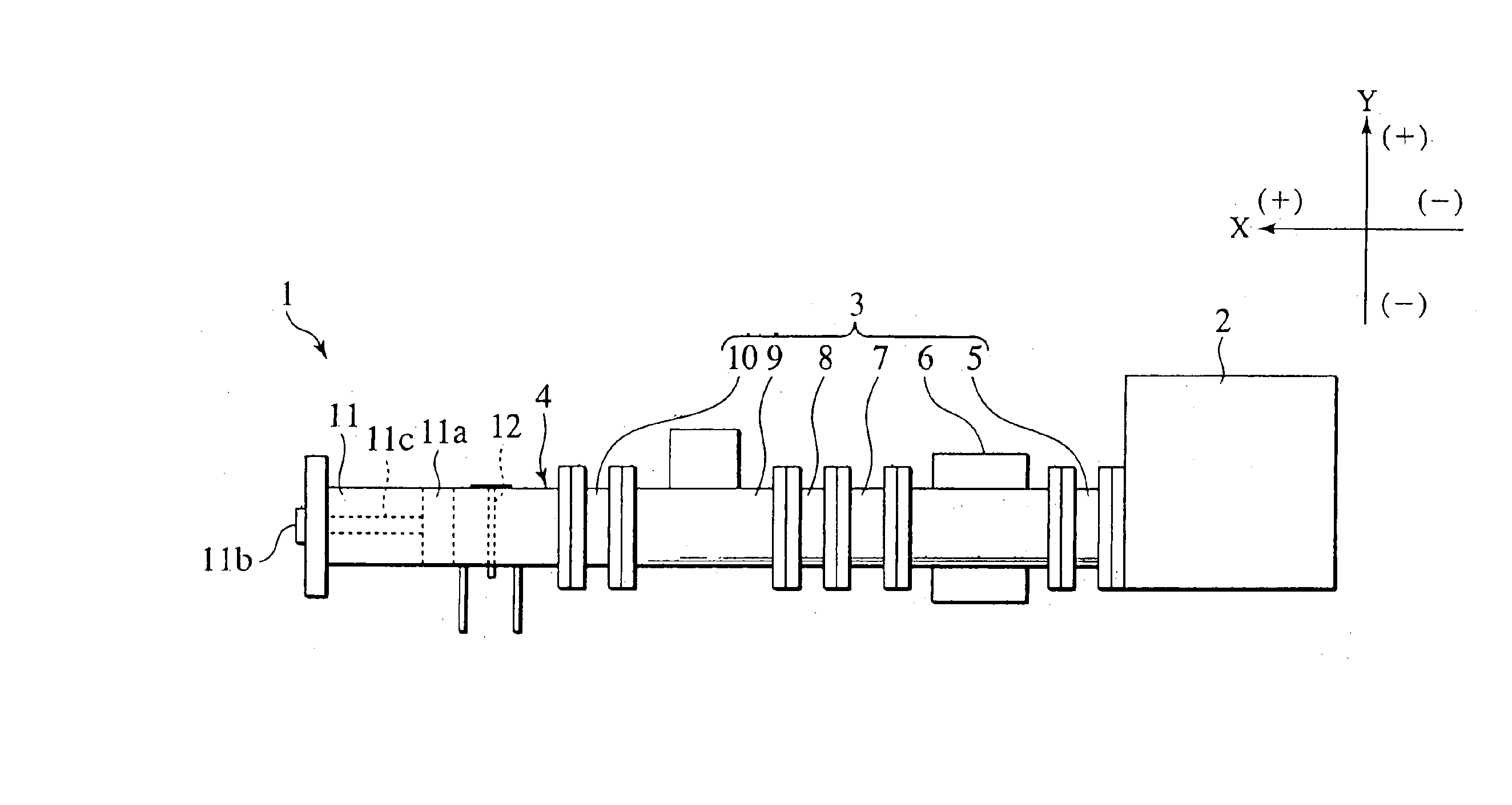
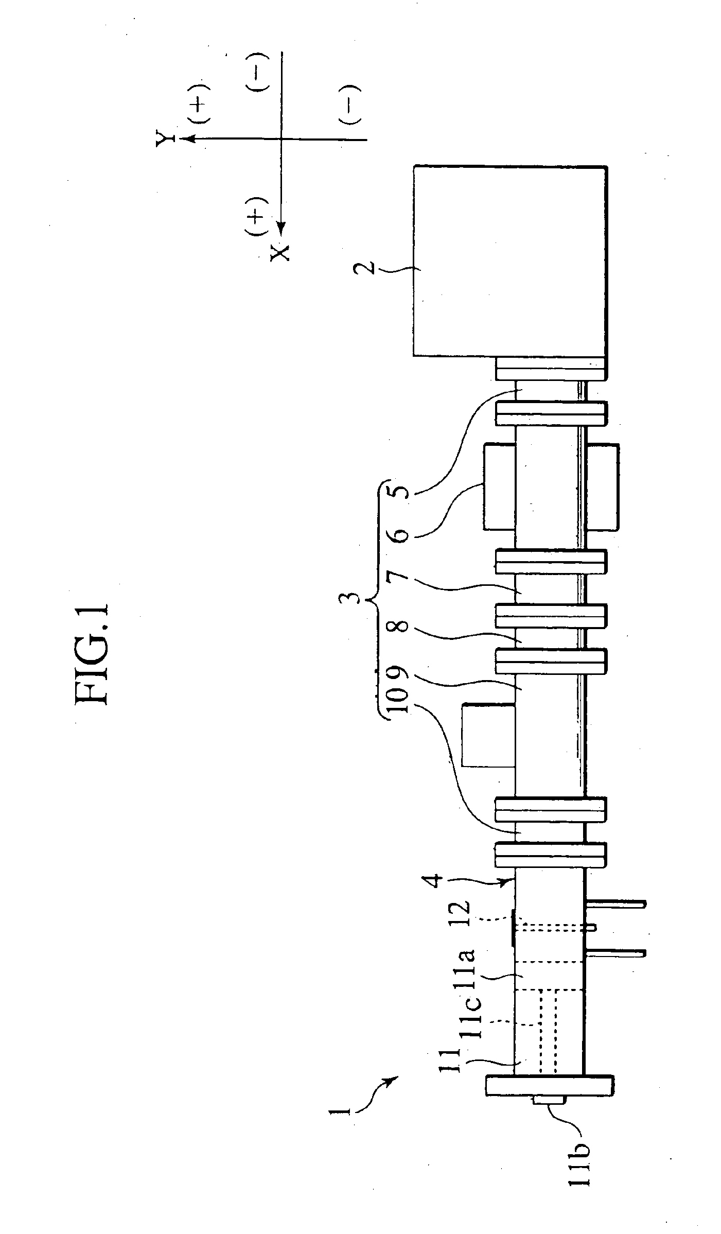
As shown in FIG. 1, a wire processing apparatus 1 is composed of a microwave generator 2 for generating microwave, a microwave transmitter 3 for transmitting microwave generated by the microwave generator 2, and a waveguide coaxial converter 4 for introducing the microwave transmitted by the microwave transmitter 3 and propagating the introduced microwave into an inner space thereof.

The microwave transmitter 3 is constituted by connecting a first direction coupler 5, an isolator 6, a second direction coupler 7, a transformer 8, an automatic matching device 9 and a transformer 10 in this order from a side of incident of microwave. Based on this structure, the microwave transmitter 3 transmits microwave toward the waveguide coaxial converter 4 with H01 wave (TE01 wave) without generating reflected wave.

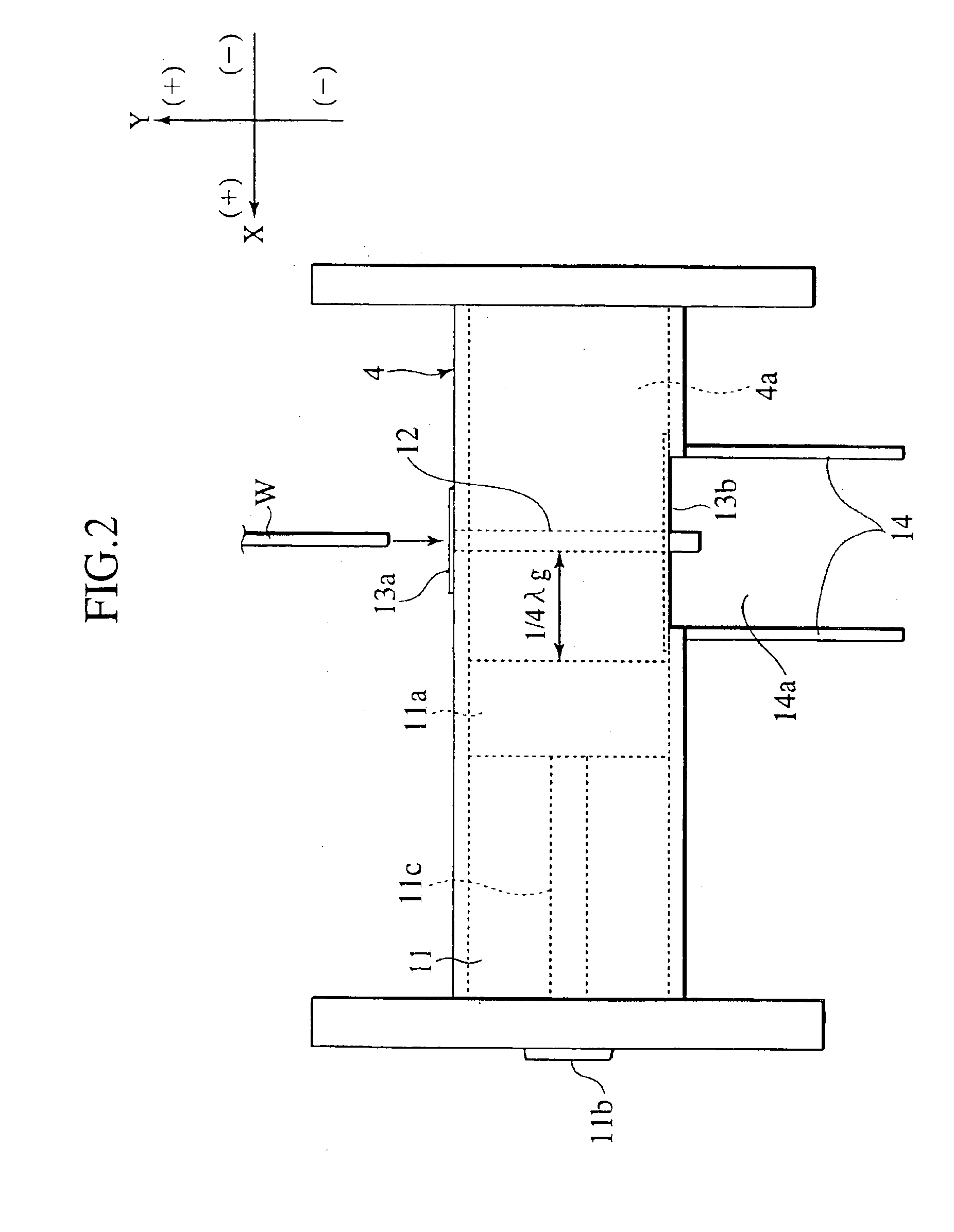
As shown in FIG. 2, the waveguide coaxial converter 4 includes a short plunger 11 on the terminal end side of a transmitting space 4a therein. The short plunger 11 has...

second embodiment

(Second Embodiment)

It is noted that a wave processing apparatus according to the second embodiment shown in FIGS. 4, 5 and 6 is almost the same as that of the wave processing apparatus according to the first embodiment shown in FIGS. 1, 2 and 3 and like parts are designated by like numbers.

As shown in FIG. 4, a wire processing apparatus 1 is composed of a microwave generator 2 for generating microwave, a microwave transmitter 3 for transmitting microwave generated by the microwave generator 2, and a waveguide coaxial converter 4 for introducing the microwave transmitted by the microwave transmitter 3 and propagating the introduced microwave into an inner space thereof.

The microwave transmitter 3 is constituted by connecting a first direction coupler 5, an isolator 6, a second direction coupler 7, a transformer 8, an automatic matching device 9 and a transformer 10 in this order from a side of incident of microwave. Based on this structure, the microwave transmitter 3 transmits micro...


PUM


Abstract

A wire processing apparatus includes a microwave generator, a microwave transmitter, a waveguide coaxial converter and a wire insertion pipe, and the wire insertion pipe is disposed in the wireguide coaxial converter. In wire recycling process, after a tip end of a coated wire is inserted into the wire insertion pipe, microwave is launched into the inside of the waveguide coaxial converter. The tip end of the coated wire is separated into a decomposed coating insulator and a molten electric conductor by microwave. In wire cross-linking process, after microwave is launched into the inside of the waveguide coaxial converter, the coated wire is inserted into the wire insertion pipe. The coated wire is cross-linked by high frequency heat and a coating insulator is adhered well to an electric conductor by heat shrinking.

Description

BACKGROUND OF THE INVENTION1. Field of the InventionThe present invention relates to a wire processing apparatus and a wire processing method for separating and recovering an electric conductor from a coated wire and for heating a coated wire to cross-link a coating insulator and adhere well the coating insulator to an electric conductor by heat shrinking.2. Description of the Related ArtIn present technical state, most of coated wires such as wire harnesses are not recycled. However, in order to encourage resource conservation and reduce load applied to environment, it is important to recycle the coated wires. As a technique allowing us to recycle a coated wire, there exits a peeling process to peel off a coating resin from a coated steel pipe. The peeling process is disclosed in Japanese Patent Application Laid-Open No. 7-214557. In the peeling process, high frequency dielectric heat is applied to the coated steel pipe, and the coating resin having coated a surface of the steel pi...

Claims


Application Information

Patent Timeline
IPC IPC(8): B29B17/02C22B7/00C22B15/00H01B15/00H01B13/00H05B6/78
CPCB29B17/02C22B7/001C22B15/0056H01B13/0016H01B13/003H01B15/00H01B15/003H05B6/701H05B6/705H05B6/788Y10T29/49169B29K2705/10B29L2031/3462B29L2031/707Y10T29/53213Y10T29/5187Y10T29/532Y10T29/49213Y10T29/514Y10T29/49117B29K2705/00Y10T83/0333Y02W30/62Y02W30/82Y02P10/20
Inventor KATO, TATSUYAKANDO, MASASHI
Owner YAZAKI CORP
Why Eureka
Try Eureka