Digital measuring instrument having flexible measuring line

a digital measuring instrument and flexible technology, applied in the field of electronic tape measures, can solve the problems of frequent damage of tape measures, high maintenance and replacement costs, and large volume of tape measures, and achieve the effect of quick and easy installation

Inactive Publication Date: 2005-03-22
SOLAR WIDE INDAL
View PDF43 Cites 33 Cited by
  • Summary
  • Abstract
  • Description
  • Claims
  • Application Information

AI Technical Summary

Benefits of technology

The digital tape measure desirably includes a printed circuit board including electronic circuitry in communication with the optical sensor. The electronic circuitry is selected from the group consisting of analog circuitry and digital circuitry. The printed circuit board also preferably includes one of more microprocessors having one of more subroutines stored therein for operating the electronic circuitry. The electronic circuitry preferably operates in conjunction with software that enables a user to re-calibrate the unit for different types of line diameters and / or line materials. The calibration data is permanently stored in memory, even when battery power is out and even if battery power is not used. As a result, a user may change the measuring line to use a line having a different diameter or material, and then re-calibrate the unit to work accurately with the new measuring line. In certain preferred embodiments, the software is adapted to count pulses for a predetermined length of measuring line that passes the optical sensor. In one particular preferred embodiment, the software is adapted to count two (2) pulses for each 1 mm (0.04″) of measuring line, thereby ensuring maximum precision and accuracy.
The measuring line drawn from the storage spool is preferably flexible. In certain preferred embodiments, the measuring line is made from a material selected from the group consisting of cotton, metal and synthetic materials such as nylon and polyester. In one preferred embodiment, the measuring line is string. In another preferred embodiment, the measuring line is made of stainless steel. The measuring line is wound about the storage spool and has a length of approximately 750 to 1500 meters. Although not limited by any particular theory of operation, it is believed that using a measuring line, as opposed to a wide measuring tape, enables a longer length of measuring material to be wound about a storage spool. As is well known to those skilled in the art, a conventional measuring tape has substantial thickness and width that occupies a substantial amount of space on a storage spool. This dramatically limits the length of measuring tape that may be stored in a hand carried tape measure. In contrast, the present invention provides an elongated, flexible measuring line that has minimal width and thickness. As a result, a substantially longer length of material may be wound about a storage spool, thereby maximizing the distance that can be measured using the present invention.
In certain preferred embodiments, the housing includes a well adapted to receive the storage spool and a removable cover securable over the well. The side cover includes a lock for selectively uncovering the well. As a result, a storage spool having worn or damaged measuring line wound about it may be replaced with another storage spool having new or repaired measuring line. Thus, the removable side cover enables a replacement storage spool with measuring line to be quickly and easily installed in the housing.
The present invention also preferably includes a measuring drum assembly including the measuring drum, whereby the measuring drum is mounted on a shaft carrying a first gear that is mechanically coupled with the rotating disc in communication with the optical sensor. The measuring line is threaded through the measuring drum assembly so that movement of the measuring line causes simultaneous rotation of the measuring drum. Due to the gear and shaft linkages described above, rotation of the measuring drum causes simultaneous rotation of the disc. In certain preferred embodiments, the measuring drum includes at least one stationary guide, at least one roller guide, and at least one cleaner guide for cleaning an exterior surface of the line. For example, if the measuring line is made of cotton, the cleaner guide may remove extraneous matter present at an outer surface of the measuring line. Thus, the measuring drum assembly defines a threaded path for the measuring line as the measuring line passes between the storage spool and the opening in the hingeable front cover of the housing. The measuring drum assembly preferably maintains at least a section of the measuring line in non-slip engagement with the surface of the measuring drum, and maintains the measuring line under tension. As used herein, the term “non-slip surface” means that there will be no slippage between movement of the measuring line and the outer annular surface of the measuring drum.

Problems solved by technology

Tape measures having distances of over one hundred meters are rare because longer tapes will substantially increase the overall size of the tape measure housing, thereby making the tape measure extremely bulky and burdensome to operate.
Another problem with conventional tape measures relates to maintenance and replacement costs.
Tape measures are frequently damaged because they are used in harsh environments resulting in the measuring tape being damaged.
A damaged measuring tape cannot accurately measure a distance or cannot be rewound onto a storage spool.
As a result, the measuring tape must be repaired or replaced at substantial cost.
Another problem relates to the accuracy of electronic tape measures.
Many conventional electronic tape measures are inaccurate or unreliable because they don't account for the hanging radius of the measuring tape on the storage spool as the tape is unwound from the storage spool.

Method used


Image

  • Digital measuring instrument having flexible measuring line
  • Digital measuring instrument having flexible measuring line
  • Digital measuring instrument having flexible measuring line

Examples


Embodiment Construction

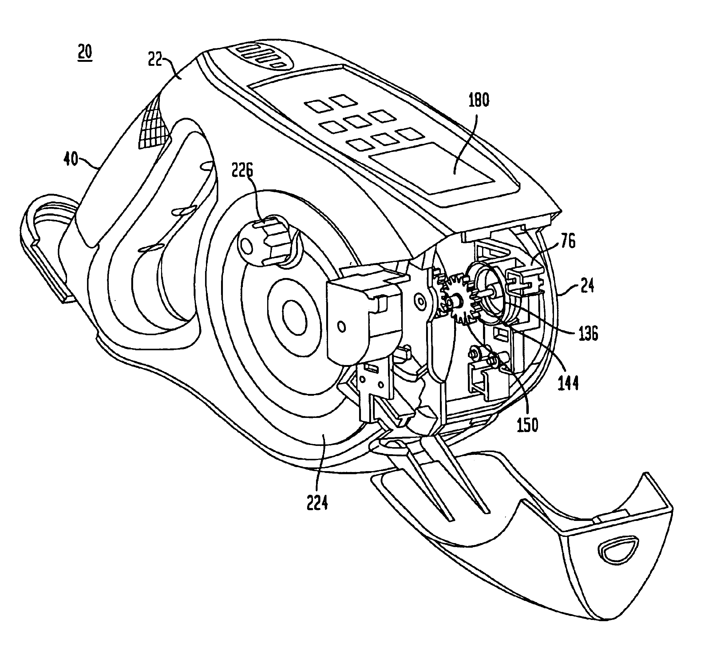
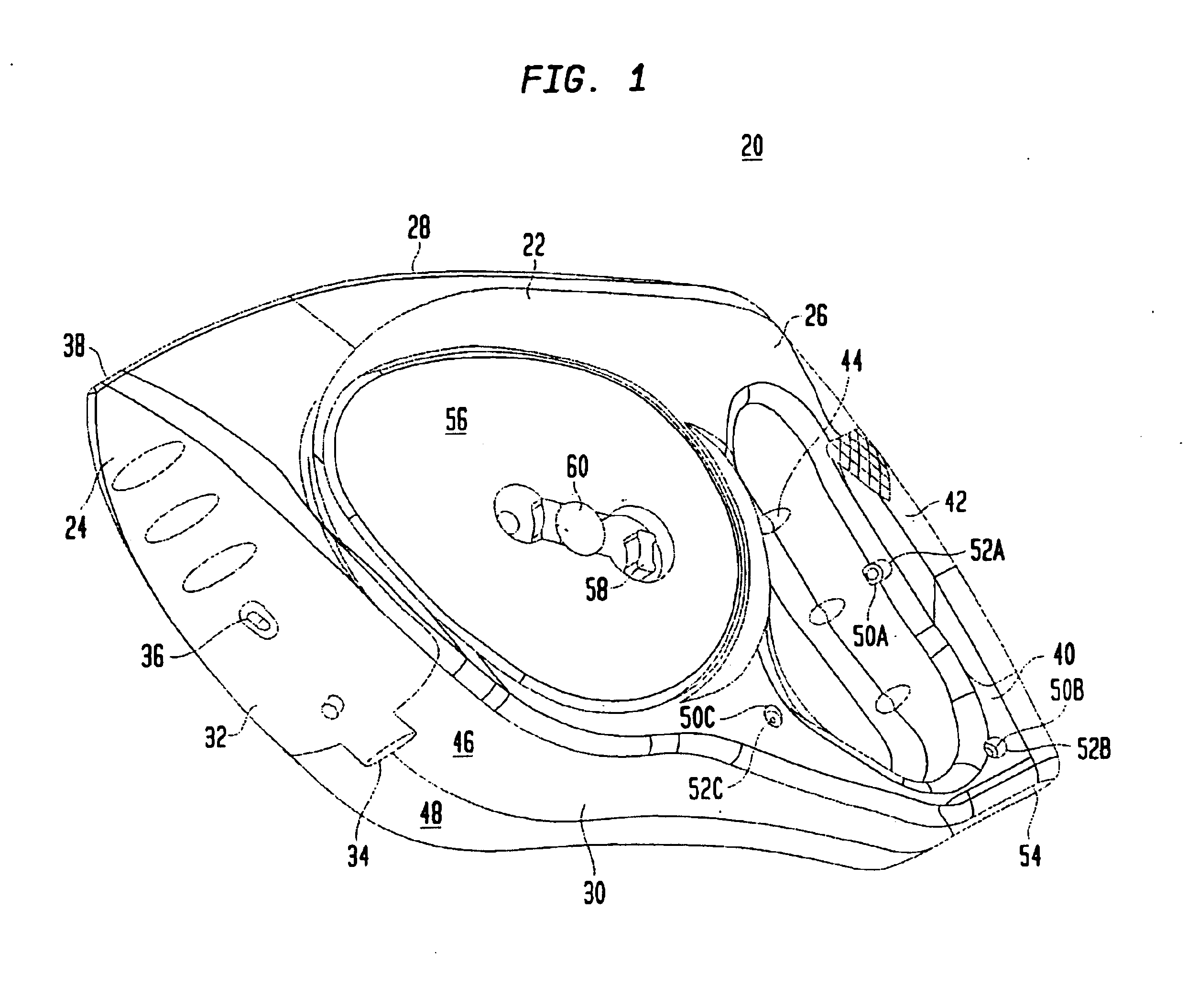
FIG. 1 shows a digital tape measure 20 including a housing 22 having a front 24, a rear 26, atop a bottom 30. In certain preferred embodiments, housing 22 is made of molded plastic. Housing 22 includes a hingeable front cover 32 movable between open and closed positions. Hingeable front cover 32 includes a cutting element 36 attached thereto for selectively cutting or trimming a measuring line (not shown). Hingeable front cover 32 includes an opening 38 through which the measuring line can be drawn from housing 22.

Housing 22 also includes a handle 40 that extends along rear 26 between the top and bottom 28, 30 of housing 22. Handle 40 is preferably integrally molded with the housing 22. A gripping surface 42 is preferably secured over an exterior surface of handle 40 for improving the gripability of the handle. The handle 40 also preferably includes one or more finger grooves 44 for enhancing a user's grip.

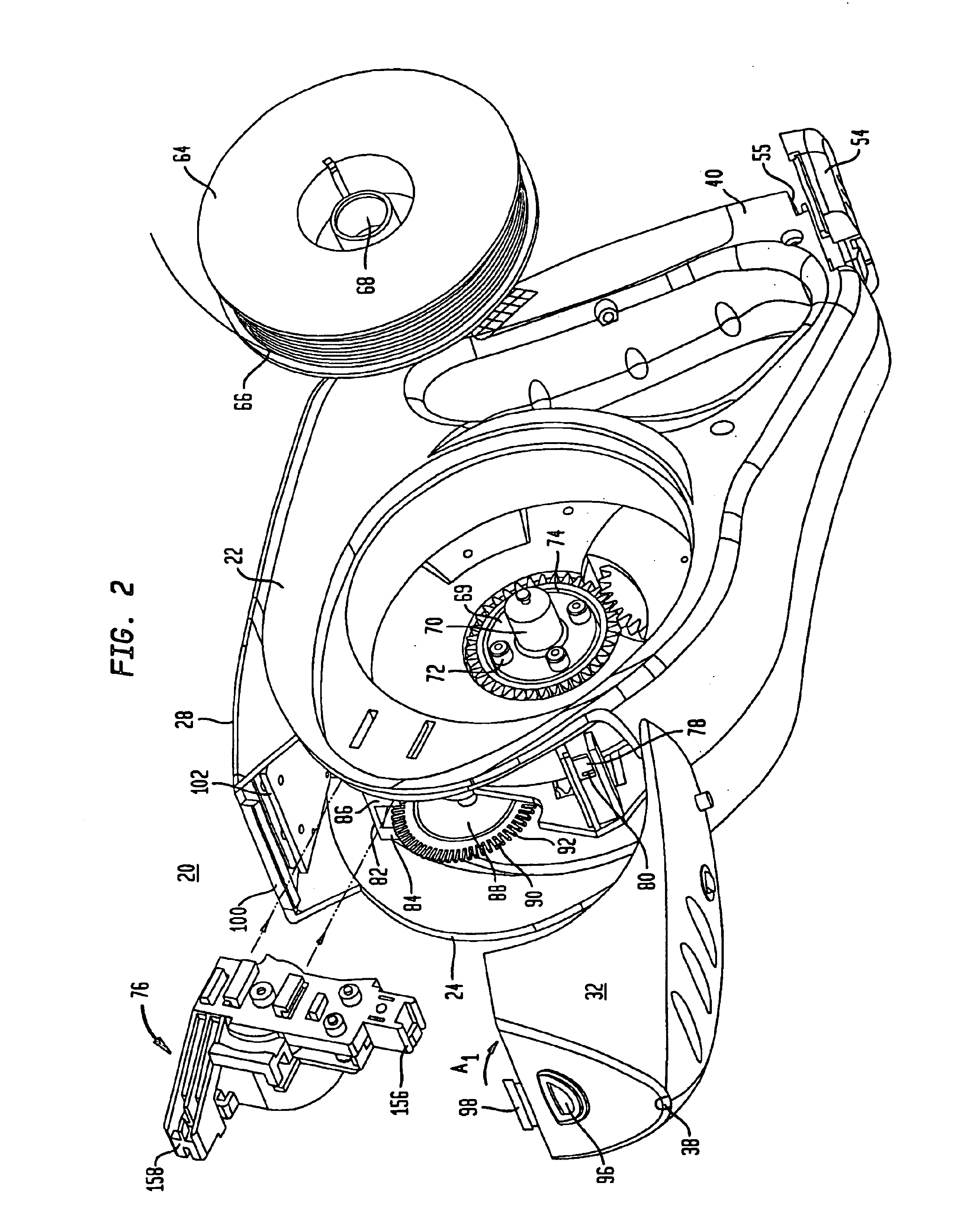
Housing 22 preferably includes a first molded part 46 and a second molded par...


PUM


Abstract

A digital measuring instrument includes a housing containing a measuring line, a rotatable drum engaging the line whereby movement of the line causes rotation of the drum, a storage spool mounted in the housing for storing the line, a crank assembly for rotating the storage spool for winding the measuring line about the storage spool, and a rotatable disc that rotates simultaneously with the measuring drum. The instrument includes an optical sensor in communication with the rotatable disk for compiling data related to rotation of the disk, and electronic circuitry in communication with the optical sensor for calculating a length of the line drawn from the housing. The housing has a well for receiving the storage spool and a side cover with a slideable lock for covering the well.

Description

FIELD OF THE INVENTIONThe present invention is related to tape measures used for measuring distances and is specifically related to electronic tape measures.BACKGROUND OF THE INVENTIONTape measures have been used for many years to accurately measure distances between two points and the lengths of objects. Tape measures typically include a housing having an opening through which a measuring tape is drawn. The measuring tape has indicia printed thereon that are used to measure distances. When measuring a distance, the measuring tape is unwound from a storage spool as it is drawn through the opening of the housing. When the measuring task is complete, the measuring tape is rewound onto the storage spool.In recent years, electronic tape measures have been developed which electronically track the length of a measuring tape unwound from a storage spool. Electronic tape measures typically include a reading element in communication with the storage spool that generates electric pulses corre...

Claims


Application Information

Patent Timeline
Patent Type & Authority Patents(United States)
IPC IPC(8): G01B3/11G01B3/10G01B3/02
CPCG01B3/11G01B2003/1094G01B2003/1069G01B3/1094G01B3/1069
Inventor SANONER, HUGHES
Owner SOLAR WIDE INDAL
Why Eureka
Try Eureka