Turbine spring clip seal

a technology of turbine springs and seals, applied in the field of sealing systems, can solve the problems of limiting the ability of the seals to prevent air leakage, high engine performance variability, and unsatisfactory results, so as to reduce the stress and load, increase the efficiency of the turbine engine, and reduce the effect of leakag

Inactive Publication Date: 2005-03-22
SIEMENS ENERGY INC
View PDF19 Cites 32 Cited by
  • Summary
  • Abstract
  • Description
  • Claims
  • Application Information

AI Technical Summary

Benefits of technology

In another embodiment, the spring clip seal may include a center sealing member positioned between the inner housing and the outer housing and may be configured to prevent a fluid from passing therebetween. In one embodiment, the center sealing member includes a plurality of leaves formed by slots. The inner and outer housings may also include slots forming leaves between adjacent slots. The center sealing member may be positioned relative to the outer housing so that the leaves of the center sealing member align with the slots of the outer housing, thereby preventing a fluid from passing through the outer housing slots. The center sealing member may also be aligned so that its leaves are aligned with slots in the inner housing, or alternatively, the leaves of the center sealing member may also be aligned with the slots of the inner housing in addition to the slots of the outer housing.
An object of this invention includes, but is not limited to, increasing the efficiency of a turbine engine by preventing a fluid, such as common air, from leaking between an inner housing and an outer housing of a seal while the fluid is directed to pass through a center aperture in the seal.
An advantage of this invention is that the turbine spring clip seal reduces leakage, and may stop leakage, between an inner housing and an outer housing of the spring clip seal.
Another advantage of this invention is that this turbine spring clip seal experiences reduced levels of stress and load during operation of a turbine engine in which the turbine spring clip seal may be mounted. Each leaf of the turbine spring clip seal experiences reduced stress levels. Thus, the turbine spring clip seal may be formed from reduced numbers of leaves, which in turn reduces the number of slots through which air may pass. The reduction in the number of leaves of the spring clip relative to conventional spring clips reduces the leakage of air through the turbine spring clip.

Problems solved by technology

Such leakage can often cause undesirable outcomes.
For instance, air leakage at this level can cause high engine performance variability, which is characterized by high NOx emissions, high dynamics or flashback, or any combination thereof.
However, the number of slots contained in conventional seals limits the ability of the seals to prevent air leakage.

Method used


Image

  • Turbine spring clip seal
  • Turbine spring clip seal
  • Turbine spring clip seal

Examples


Embodiment Construction

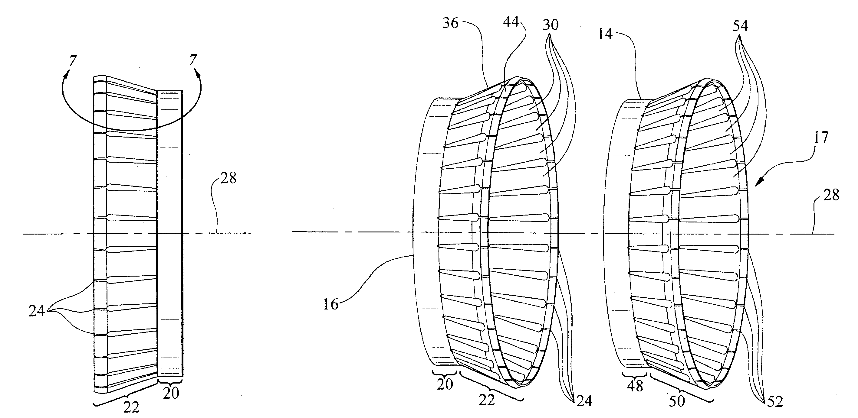
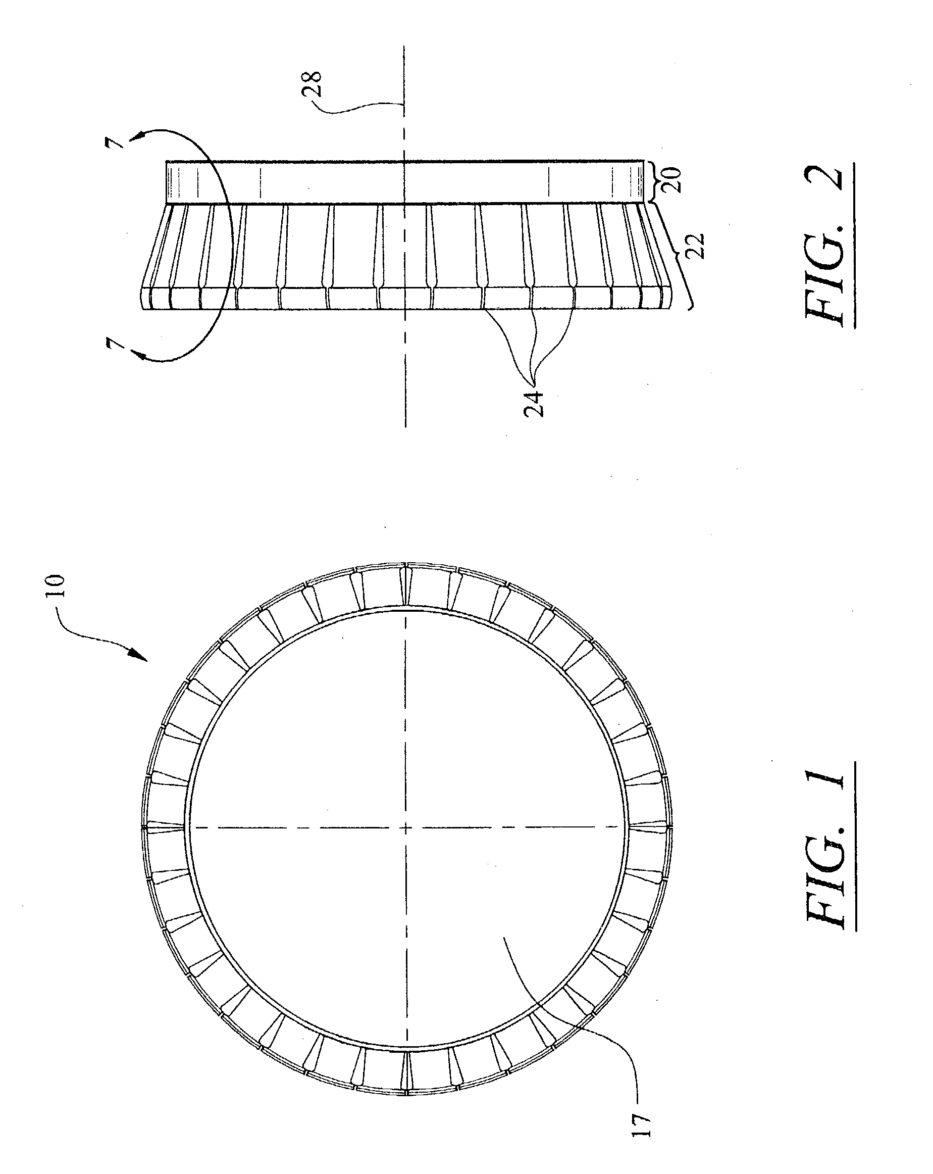
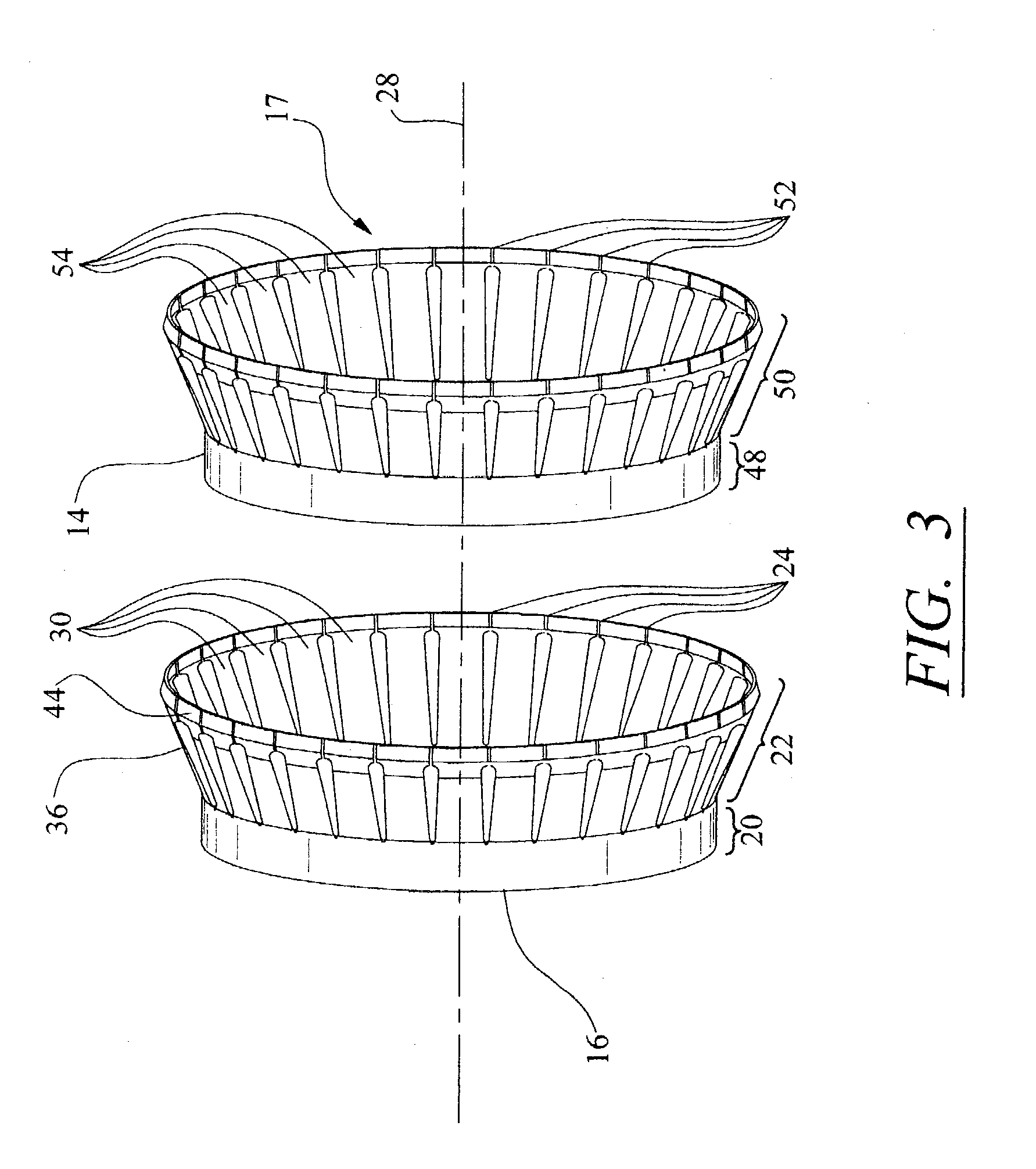
Referring to FIGS. 1 and 2, a turbine spring clip seal 10 can be configured as a generally cylindrical- or ring-shaped assembly, including an outer housing 16 and an inner housing 14. A turbine spring clip seal 10, such as one according to the invention, is usable in turbine engines to direct gases to mix with fuel flowing into a conventional combustor basket 12 (see FIG. 10). The spring clip seal is intended to direct fluid flow and to prevent at least a portion of air directed through the center aperture 17 in the turbine spring seal from leaking between the inner and outer housings 14 and 16. The flow region within the center aperture 17 is relatively lower in pressure than the region outside housing 14, so that fluid leakage generally occurs from the outside in. In an alternative embodiment of this invention, the turbine spring clip seal 10 may include a center sealing member 66.

As shown in FIGS. 1–5, the turbine spring clip seal 10 may be formed from an outer housing 16 and an...


PUM


Abstract

An improved turbine spring clip seal for directing gases to be mixed with fuel in a combustor basket. The turbine clip seal may include an inner housing and an outer housing. The inner housing or the outer housing, or both, may include one or more tapered leaves forming a portion of the spring clip seal. At least one leaf may include a flared end for limiting gas from passing through the slots in the spring clip seal. In at least one embodiment, the turbine clip seal may include a center sealing member positioned between the inner and outer housings.

Description

FIELD OF THE INVENTION The present invention relates in general to sealing systems and, more particularly, to an improved turbine spring clip seal for directing gases to mix with fuel in a combustor basket in a turbine engine. BACKGROUND OF THE INVENTION There exists a plethora of variables that affect performance of a turbine engine. One such variable that has been identified in dry-low NOx (DLN) combustor design turbines is the air flow distribution between the combustor zone and the leakage air flows. Typically, a spring clip seal is used in such a turbine engine to direct gases, such as common air, into a combustor basket where the air mixes with fuel. Conventional spring clip seals direct air through center apertures in the seals and are formed from outer and inner housings. The seals are generally cylindrical cones that taper from a first diameter to a second, smaller diameter. The first diameter is often placed in contact with a transition inlet ring, and the second, smaller ...

Claims


Application Information

Patent Timeline
Patent Type & Authority Patents(United States)
IPC IPC(8): F01D11/00F23R3/60F23R3/00
CPCF23R3/60F01D11/005
Inventor PARKER, DAVID M.
Owner SIEMENS ENERGY INC
Why Eureka
Try Eureka