Supporting structure of sub-frame in suspension system for vehicle

a technology of supporting structure and suspension system, which is applied in the direction of steering linkage, pivoted suspension arms, transportation and packaging, etc., can solve the problems of difficult control of vibration and sound effects of the sub-frame, and achieve the effect of improving rust prevention effect, increasing the productivity of the stay, and increasing the durability of the stay

Inactive Publication Date: 2005-03-22
SUBARU CORP
View PDF18 Cites 55 Cited by
  • Summary
  • Abstract
  • Description
  • Claims
  • Application Information

AI Technical Summary

Benefits of technology

A tenth object of the present invention is to provide the sub-frame support structure, wherein it is easy to appropriately locate the elongated hollow member with respect to the body frame-side fixation fitting, and welding of the elongated member to the body frame-side fixation fitting is easily performed, so that the productivity of the stay can be increased, by the body frame-side fixation fitting comprising a fixing part, a supporting part and an insertion hole, the fixing part fixed to the body frame, the supporting part being integral with the fixing part, and extends in a direction which crosses with a central axis of the elongated hollow member, the insertion hole provided on the supporting part for accepting the second end of the elongated hollow member and being subjected to welding.
A eleventh object of the present invention is to provide the sub-frame support structure, wherein earth mud and sand entered into the elongated hollow member come out of themselves, it is easy to wash the inside of the elongated hollow member, and the durability of the stay is increased by improving a rust prevention affect, by the at least one stay connects the inner cylinder lower edge and the body frame, at least one of the first end and the second end of the elongated hollow member located at a position below than a center part of the elongated hollow member between the bushing-side fixation fitting and the body frame-side fixation fitting.
A twelfth object of the present invention is to provide the sub-frame support structure, by which the displacement of the sub-frame in longitudinal directions of the first and the second stays for decreasing the vibrations in order to attain an excellent drivability and stability, and a stay is deformed by bending in a predetermined direction when the load is applied to the stay in a predetermined direction so as not to influence the equipments or members provided near the stay, by the at least one stay comprising at least one first stay and at least one second stay, the at least one first stay extending along the body frame, the bushing-side fixation fitting of the at least one first stay being supported on the inner cylinder lower edge, and the body frame-side fixation fitting of the at least one first stay being supported on the body frame, and the at least one second stay extending along the body frame in a different direction from the at least one first stay, the bushing-side fixation fitting of the at least one second stay being supported on the inner cylinder lower edge, and the body frame-side fixation fitting of the at least one second stay being supported on the body frame.
A thirteenth object of the present invention is to provide the sub-frame support structure, by which the displacement of the sub-frame in the lengthwise direction of the vehicle body and in the widthwise direction is restrained, the change of the toe-angle is minimized, and the drivability and stability are improved by the body frame comprising a pair of main frames, each extending in a lengthwise direction and spaced from each other in a vehicle widthwise direction, and a body cross member extending in a vehicle widthwise direction connecting the main frames, the at least one first stay comprising a pair of the first stays, and the first stays respectively extending along the main frames, each of the first stays connects the inner cylinder lower edge and one of the main frames, and the at least one second stay extending along the body cross member in a vehicle widthwise direction and connects the inner cylinder lower edge and the body cross member.
A fourteenth object of the present invention is to provide the sub-frame support structure, by which the first stays resist the load in the lengthwise direction of the vehicle body, the displacement of a rear part of the sub-frame and hence the displacement of a front part of the sub-frame in the lengthwise direction can be restricted, and rotational distortion / displacement of the sub-frame is also prevented when a load applied to suspension members is transmitted to either of left or right side of the sub-frame in the lengthwise direction of the vehicle body, by the sub-frame containing a sub-frame front part and a sub-frame rear part, by the at least one elastic bushings comprising elastic bushings provided on the sub-frame front part and elastic bushings provided on the sub-frame rear part, each of the first stays extending in a lengthwise direction connects an inner cylinder lower edge of one of the elastic bushings provided on the sub-frame front part and one of the main frames, and the at least one second stay comprising a pair of second stays, and each of the second stays extending in a vehicle widthwise direction connects an inner cylinder lower edge of one of the elastic bushings provided on the sub-frame rear part and the body cross member.
A fifteenth of the present invention is to provide the sub-frame support structure, wherein the displacement in the vehicle widthwise direction is restricted to a large extent by further increasing a support strength of the second stay via the elastic bushings, and the drivability and stability are further improved, by the at least one second stay extending along the body cross member in a vehicle widthwise direction as a single body in approximately a straight line, a first end of the second stay being supported on an inner cylinder lower edge provided on one of the main frames, a second end of the second stay being supported on an inner cylinder lower edge provided on another of the main frames.

Problems solved by technology

By this measure, however, it becomes difficult to control the vibration and sound effects to the sub-frame 10 from the load applied to the suspension.

Method used


Image

  • Supporting structure of sub-frame in suspension system for vehicle
  • Supporting structure of sub-frame in suspension system for vehicle
  • Supporting structure of sub-frame in suspension system for vehicle

Examples


first embodiment

(First Embodiment)

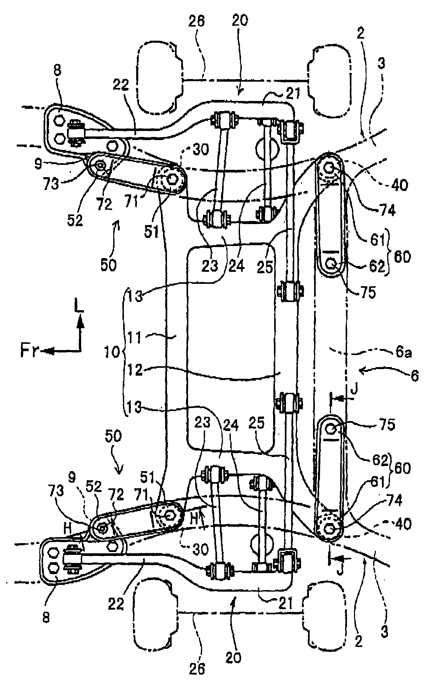
FIG. 1 is a bottom view of a vehicle at a back side thereof for explaining a supporting structure of sub-frame as a first embodiment of the present invention. In the figure, members corresponding to those in FIG. 12 are indicated by the same reference numerals, and the detailed explanations on these common members are omitted.

Each of main frame 2 and body cross member 6 has a cross-section in a U shape with a top being opened. The top is fixed to a bottom surface of a vehicle body (not shown) to close the top. On bottom faces 3 of the main frames 2 at parts where the body cross member 6 is connected, elastic bushings 40 are provided for supporting both ends of a rear sub-frame 12. In a front part of the vehicle body of the prior art, elastic bushings 30 are provided for supporting both ends of a front sub-frame 11 on the main frames 2.

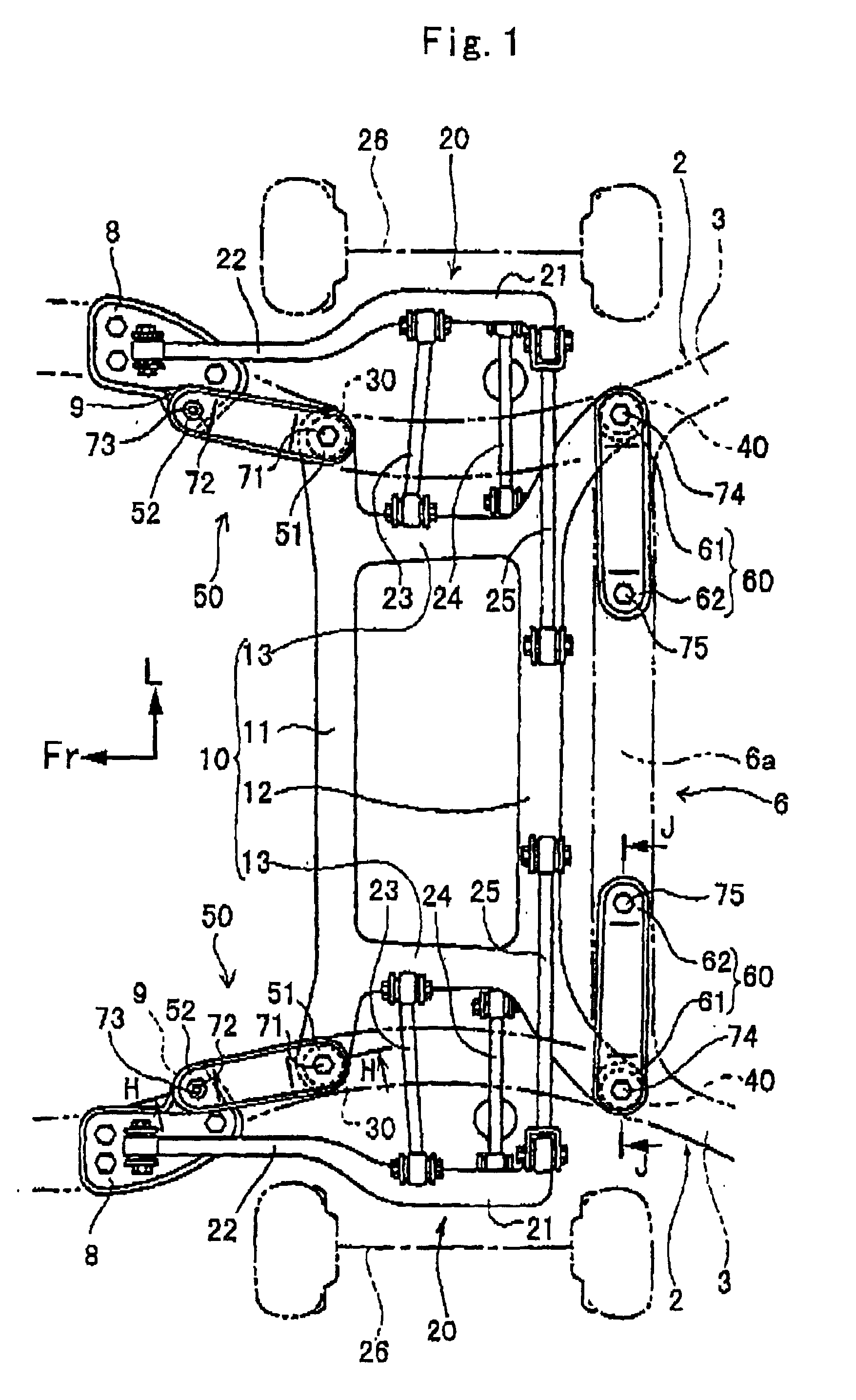
FIG. 2 is a cross-section of a part shown in FIG. 1 cut along H—H. As shown in FIG. 2, the elastic bushing 30 has an inner cylinder ...

second embodiment

(Second Embodiment)

FIG. 4 is a partial diagram for explaining a supporting structure of sub-frame as a second embodiment of the present invention. In the figure, members corresponding to those in FIG. 1 are indicated by the same reference numerals, and the detailed explanations on these common members are omitted. The characteristic point of the second embodiment is that a pair of second stays 60 which are provided on the right and left sides of the body in the first embodiment is replaced by a second stay 80 as an integral body extending approximately in a straight line in the widthwise direction, and a center part 83 of the stay 80 with respect to the widthwise is fixed by an installation bolt on a bottom face 6a of the body cross member 6.

The second stay 80 approximately has a planer shape having a flange erected from the entire periphery similarly to the first embodiment. A first end 81 of the second stay 80 is supported on a lower edge of the elastic bushing 40 provided on one ...

third embodiment

(Third Embodiment)

FIG. 5 is a partial diagram for explaining a supporting structure of sub-frame as a third embodiment of the present invention. In the figure, members corresponding to those in FIG. 1 and FIG. 12 are indicated by the same reference numerals, and the detailed explanations on these common members are omitted.

FIG. 6 is the cross-section of a part shown in FIG. 5 cut along K—K. The structure shown in FIG. 6 is basically the same as that shown in FIG. 2, and the bottom face 3 of the main frame 2 is composed of the bushing surface 3A, the inclined surface 3B and the horizontal surface, 3C. A bracket 8 is fixed between the inclined surface 3B and the horizontal surface 3C for supporting the radius arm 22 on the main frame 2.

A first stay 500 extends in the lengthwise direction of the body below the bottom face 3 of the main frame 2 connecting the bracket 8 and a lower edge 3la of an elastic bushing 30.

The first stay 500 has a bushing-side fitting 510 connected with the elas...


PUM


Abstract

A supporting structure of a sub-frame for a suspension system contains a body frame, a sub-frame, elastic bushings, each having an inner cylinder having a lower edge. And an outer cylinder and an elastic member are interposed between the inner and outer cylinders. The sub-frame is supported on the body frame via the elastic bushings, at least one of first stay extends along the body frame, and at least one second stay extends along the body frame in a different direction from the first stay. Both ends of each of the fist and second stays respectively are supported on the lower edge of the inner cylinder and the body frame.

Description

BACKGROUND OF THE INVENTION1. Field of the InventionThe present invention relates to a supporting structure of a sub-frame used in a suspension system for a vehicle, particularly to the structure for supporting the sub-frame which extends in a widthwise direction of the vehicle and supports left and right suspension members through an elastic bush.2. Discussion of the Related ArtFIGS. 12, 13 and 14 are schematic drawings for illustrating a known supporting structure of a sub-frame used in a suspension system for a vehicle. An arrow indication “Fr” represents a forward direction of the vehicle, the arrow indication “L” does a leftward one seen from a back side of the vehicle toward running direction and the arrow indication “U” does an upward direction thereof shown in the figures.A body frame 1 comprises a pair of main frames 2 and a body cross member 6. Both main frames 2,2 are separately provided to extend in parallel with each other under the vehicle in a lengthwise direction (no...

Claims


Application Information

Patent Timeline
Patent Type & Authority Patents(United States)
IPC IPC(8): B60G3/18B60G25/00B60G3/20B62D21/11B60G21/055B60G99/00
CPCB60G3/20B60G21/0551B60G99/00B62D21/11B60G2200/182B60G2200/184B60G2204/15B60G2204/41B60G2204/43B60G2206/60B60G2204/1222
Inventor TATSUMI, HIDEHARUMARUO, TETSUYAMATSUKI, TOSHIYUKI
Owner SUBARU CORP
Why Eureka
Try Eureka