
Rotor/stator type homogenizer

a technology of rotor and stator, which is applied in the direction of sliding contact bearings, mechanical equipment, transportation and packaging, etc., can solve the problems of bearing wear and inability to set the gap between the stator and the rotor to be very small, and achieve the effect of increasing the rotating speed of the rotor and efficient homogenizing

Inactive Publication Date: 2005-03-22
THK CO LTD
View PDF8 Cites 44 Cited by
  • Summary
  • Abstract
  • Description
  • Claims
  • Application Information

AI Technical Summary

Benefits of technology

The present invention has been made in view of the above problems in the prior art. It is an object of the present invention to provide a rotor / stator type homogenizer which allows the gap between the rotor and the stator to be set to a very small value and which does not involve generation of foreign matter such as abrasion particles even if the rotor is rotated at high speed, making it possible to efficiently homogenize a plurality of liquids having no mutual compatibility.
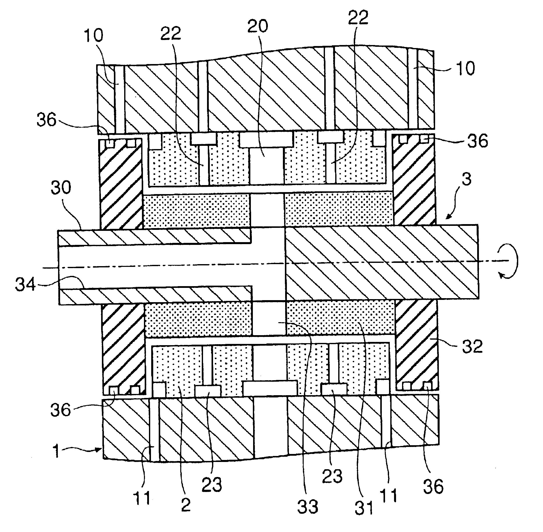
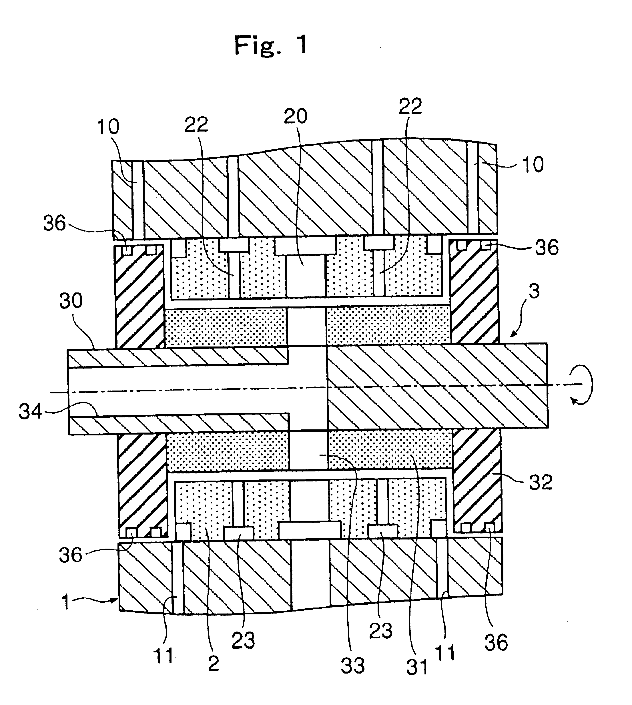
Further, when the rotation of rotor is supported by a hydrodynamic bearing, the rotor is in a floating state with respect to the stator, so that no dust or the like due to wear is generated even if the rotor is rotated at high speed, making it possible to always keep the solutions passing through the flow passages of the rotor and stator clean. Thus, it is possible to increase the rotating speed of the rotor so that the rotor can make a high speed rotation of 50000 rpm or more, thus providing a very efficient homogenizer.

Problems solved by technology

However, in the conventional rotor / stator type homogenizer, the rotor rotation is supported by a ball bearing or a sliding bearing, so that when the rotor rotation accuracy, etc. are taken into account, it is impossible to set the gap between the stator and the rotor to be very small, the lower limit size of the gap being approximately 40 μm.
Further, when the rotor rotates at high speed, there is the problem of wear of the bearing.

Method used


Image

  • Rotor/stator type homogenizer
  • Rotor/stator type homogenizer
  • Rotor/stator type homogenizer

Examples


Embodiment Construction

The rotor / stator type homogenizer of the present invention will now be described in detail with reference to the accompanying drawings.

FIG. 1 shows an example of a homogenizer to which the present invention is applied. This homogenizer sucks in a plurality of liquids having no mutual compatibility and mixes and agitates them to change them into a homogenized emulsion. It comprises a substantially cylindrical stationary housing 1, a cylindrical stator 2 secured in position in a hollow of the stationary housing 1, and a rotor 3 rotatably provided in a hollow of the stator 2.

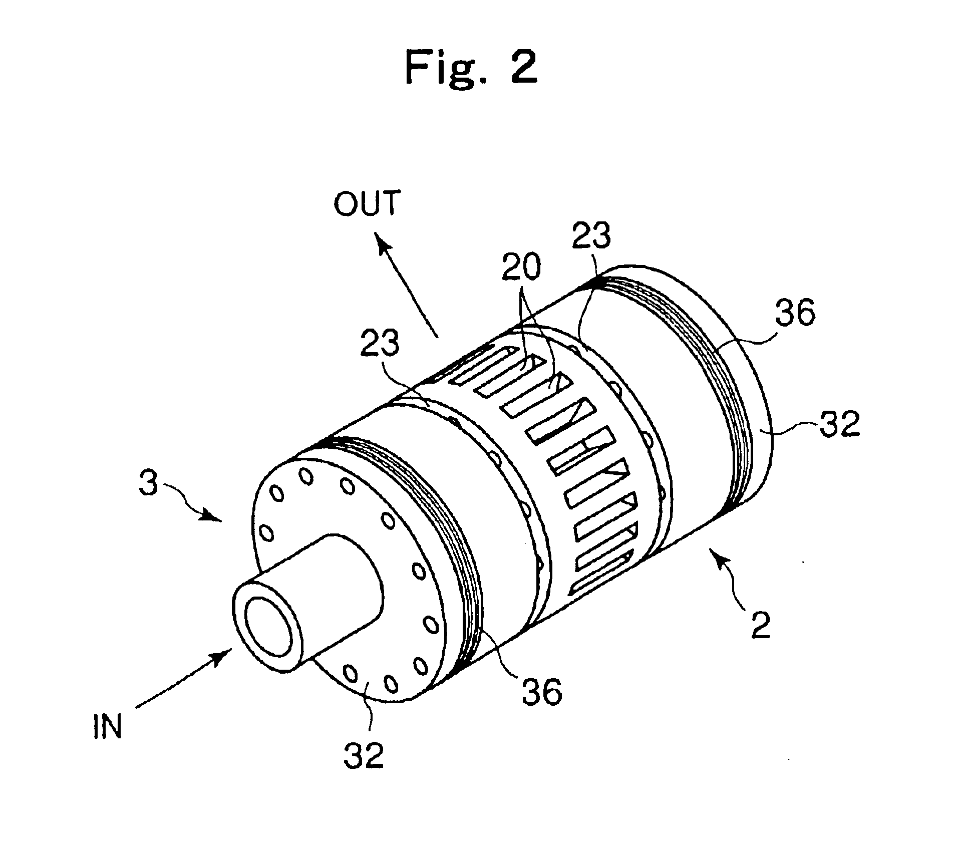
FIG. 2 is a perspective view showing the outward appearance of the stator 2 and the rotor 3, with the stationary housing 1 removed. FIG. 3 is a perspective view of the stator 2. The stator 2 is formed as a cylinder using a fine ceramic material such as silicon carbide, silicon nitride, zirconia, or alumina. In the middle portion of the stator 2 with respect to the axial direction thereof, there are circumferentiall...


PUM

PropertyMeasurementUnit
Pressureaaaaaaaaaa
Speedaaaaaaaaaa

Abstract

Disclosed is a rotor / stator type homogenizer which allows the gap between the rotor and the stator to be set to a very small dimension and which does not involve generation of abrasion particles or the like even if the rotor is rotated at high speed, making it possible to efficiently homogenize a plurality of liquids having no mutual compatibility. The inner peripheral surface of the stator and the outer peripheral surface of the rotor are opposed to each other through a predetermined gap and a portion of the solutions is introduced into the gap to form a hydrodynamic bearing, thereby supporting rotation of the rotor with respect to the stator.

Description

BACKGROUND OF THE INVENTION1. Field of the InventionThe present invention relates to a homogenizer used, for example, to mechanically mix and agitate a plurality of liquids having no mutual compatibility to obtain an emulsion. In particular, the present invention relates to an improvement of a so-called rotor / stator type homogenizer in which a rotor is rotated at high speed inside a stator having a plurality of radially formed flow passages to thereby effect mixing and agitating by utilizing a shearing force generated between the stator and the rotor.2. Description of the Related ArtHomogenizers are used to mechanically mix and agitate a plurality of liquids having no mutual compatibility as in the case of water and oil to thereby homogenize them into an emulsion. They are frequently used in production equipment for foods, chemical products, or the like, experimental plants, etc. Conventionally, there are known homogenizers of various structures, including what is called a rotor / sta...

Claims


Application Information

Patent Timeline
IPC IPC(8): B01F3/08B01F7/00F16C17/10B01F13/00B01F15/00
CPCB01F3/0807B01F7/008F16C17/10B01F7/00816B01F23/41B01F27/272B01F27/2722B01F27/00
Inventor UESUGI, MASAKAZUTSUNOFURI, MASAHIRONAGANO, JUNMIZOBUCHI, SHOTARO
Owner THK CO LTD
Learn More