Electrical junction box and method of manufacturing the same

a technology of electrical junction box and manufacturing method, which is applied in the direction of electrical apparatus casing/cabinet/drawer, gaseous cathode, coupling device connection, etc., can solve the problems of increased cost, limited mounting positions of electronic components b>65/b>, and bulky structure, so as to enhance the productivity of electrical junction box

Inactive Publication Date: 2005-03-22
YAZAKI CORP
View PDF9 Cites 54 Cited by
  • Summary
  • Abstract
  • Description
  • Claims
  • Application Information

AI Technical Summary

Benefits of technology

In such a configuration, the productivity ...

Problems solved by technology

However, this idea is not practical, because there are such inconveniences that formation of the through hole may lead to a rise of cost, and mounting positions of the electronic components 65 may be limited.
In this electrical junction box, because the electronic unit ...

Method used


Image

  • Electrical junction box and method of manufacturing the same
  • Electrical junction box and method of manufacturing the same
  • Electrical junction box and method of manufacturing the same

Examples


second embodiment

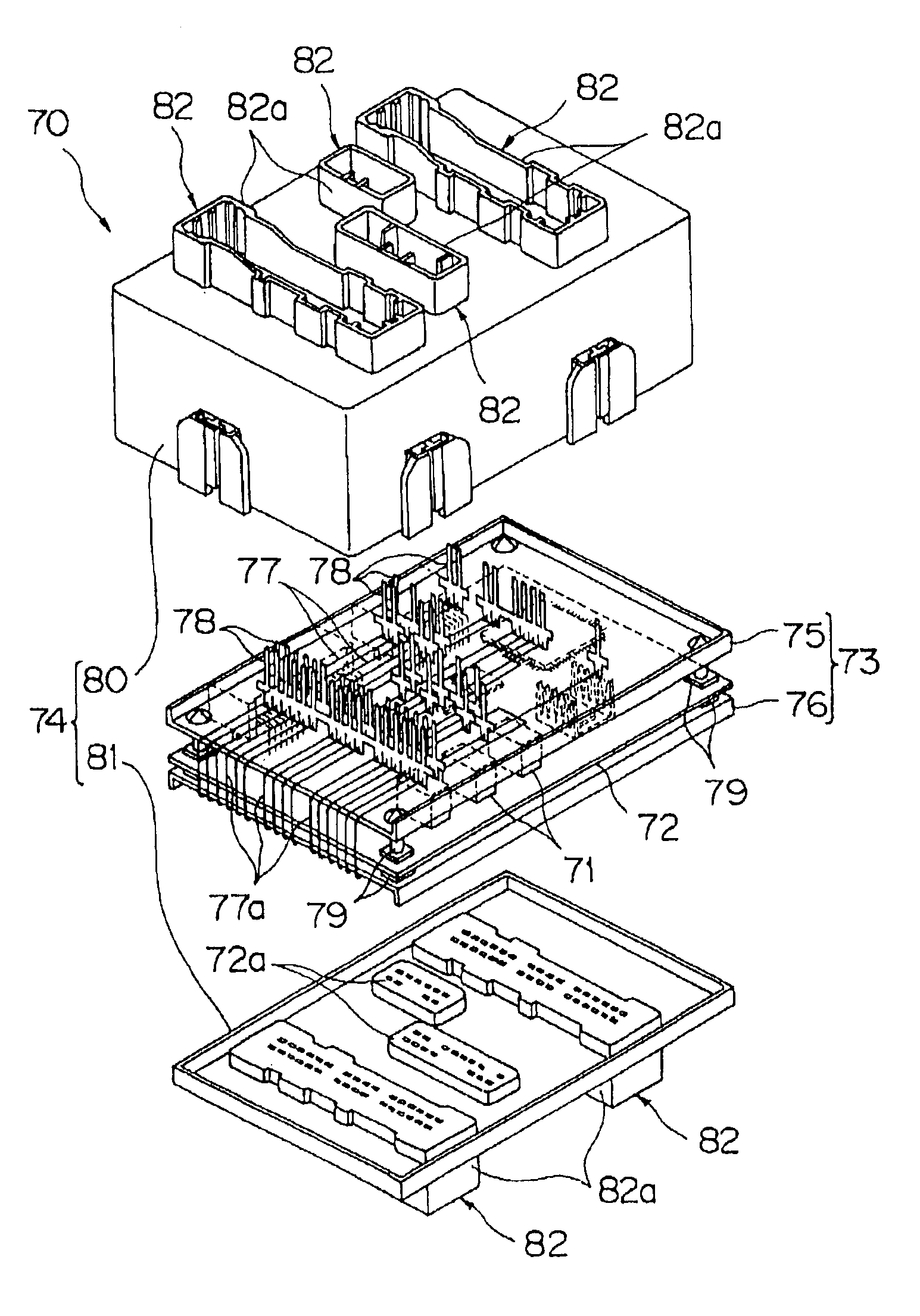
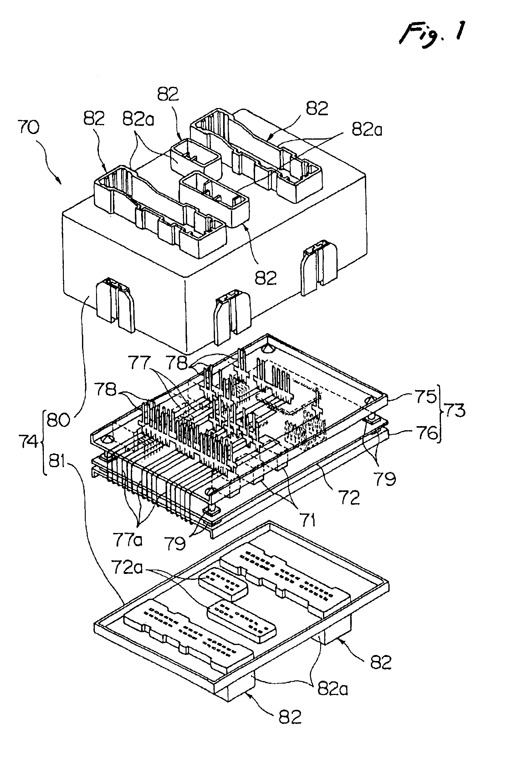
FIG. 3 shows an electrical junction box 1 according to the invention.

This electrical junction box 1 includes: two wiring boards 2, 3 made of insulating resin and arranged in parallel with each other; sheathed electric wires 4 (hereinafter referred to as electric wires) arranged on the wiring boards 2, 3; terminals 5 to 7 press-fitted to the electric wires 4; a plurality of connectors 8 and electric component mounting parts 9, 10 containing the terminals 5 to 7; an upper and lower casings 11, 12 made of synthetic resin from which the connectors 8 and the electric component mounting parts 9, 10 are projected outward; and an electronic unit 13 interposed between the two wiring boards 2, 3.

In FIG. 3, numeral 14 designates a setting table which is used on occasion of manufacturing the electrical junction box 1. The method of manufacturing the electrical junction box 1 will be described later in detail.

The electronic unit 13 is fixed to the lower wiring board 3. The lower wiring board 3 h...


PUM


Abstract

In an electrical junction box, a first board part and a second board part are arranged substantially in parallel while opposing to each other. An electric wire extends along both of the first board part and the second board part, and has a bent portion extending across a gap defined between the first board part and the second board part. An electronic unit is disposed in the gap.

Description

BACKGROUND OF THE INVENTIONThe present invention relates to an electrical junction box of a type that an electronic unit is contained therein, and also relates to a method of manufacturing such an electrical junction box.In recent years, use of the electrical junction box has become diversified, and there are some electrical junction boxes which are provided with controlling function in addition to simple power distributing function. FIG. 10 shows an example of such an electrical junction box.This electrical junction box 61 includes: a plurality of wiring boards 64 on which a number of electric wires 62 are arranged; terminals 63 for connectors to be electrically connected at appropriate positions of the arranged electric wires 62 are provided uprightly; an electronic unit 66 which is an electronic board carrying thereon electronic components 65; an upper casing 67 and a lower casing 68 which are made of electrically insulating material and adapted to contain these members.On an out...

Claims


Application Information

Patent Timeline
IPC IPC(8): B60R16/02H02G3/08H02G3/16B60R16/023
CPCB60R16/0239H05K7/026
Inventor SUZUKI, KATSUYASAKATA, HIROAKIISHIDA, YUICHISHIMIZU, KAZUHIROINABA, TATSUYA
Owner YAZAKI CORP
Why Eureka
Try Eureka