Multi-mode vibration damping device and method using negative capacitance shunt circuits

a multi-mode vibration and negative capacitance technology, applied in the field of multi-mode vibration damping devices and methods, can solve the problems of providing vibration damping in the limited frequency range, limited to the control of a single vibration mode, and conventional multi-mode vibration dampers using shunt circuits, etc., to achieve the effect of suppressing multi-mode vibration and/or noise amplitude and reducing multi-mode vibration amplitud

Inactive Publication Date: 2005-03-22
POHANG UNIV OF SCI & TECH
View PDF14 Cites 6 Cited by
  • Summary
  • Abstract
  • Description
  • Claims
  • Application Information

AI Technical Summary

Benefits of technology

The present invention provides a novel shunt circuit, which has a capability to suppress multimode vibration and / or noise amplitudes by using a pair of piezoceramic patches. A piezo patch attached on the structure with a series resistor-negative capacitor shunt circuit is designed to control the vibration amplitudes in the low frequency range. The other patch bonded below the structure with a parallel resistor-negative capacitor shunt circuit is for suppressing vibration modes in the high frequency range. In order to describe the characteristic behaviors of piezoelectric damper connected with a series and a parallel resistor-negative capacitor branch circuit, the stiffness ratio and loss factor with respect to the non-dimensional frequency are considered. The mechanism of a piezoelectric shunted circuit is also described as considering a shunt voltage generated by the shunt impedance. Thus, the piezo patches attached on the vibrating system with combined a series and a parallel resistor-negative capacitor branch circuit can significantly reduce multi-mode vibration amplitudes simultaneously across a broad frequency band. Hence, the negative capacitance shunt circuit according to the present invention establishes an invaluable tool as a multimode vibration damper in many engineering applications.

Problems solved by technology

However, these devices have, so far, been limited to control of a single vibration mode by matching the electrical resonance of the shunting device with the mechanical resonance of the vibrating structure or system.
However, the conventional multi-mode vibration damper using a shunt circuit has a drawback in that it only provides damping of vibration in the limited frequency range.

Method used


Image

  • Multi-mode vibration damping device and method using negative capacitance shunt circuits
  • Multi-mode vibration damping device and method using negative capacitance shunt circuits
  • Multi-mode vibration damping device and method using negative capacitance shunt circuits

Examples


Embodiment Construction

A multi-mode vibration damper using negative capacitance shunt circuits according to the present invention will now be described more fully with reference to the accompanying drawings.

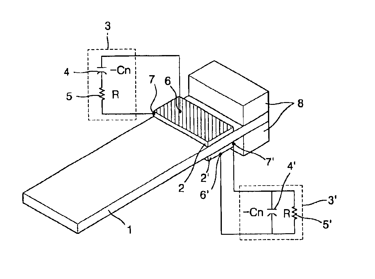
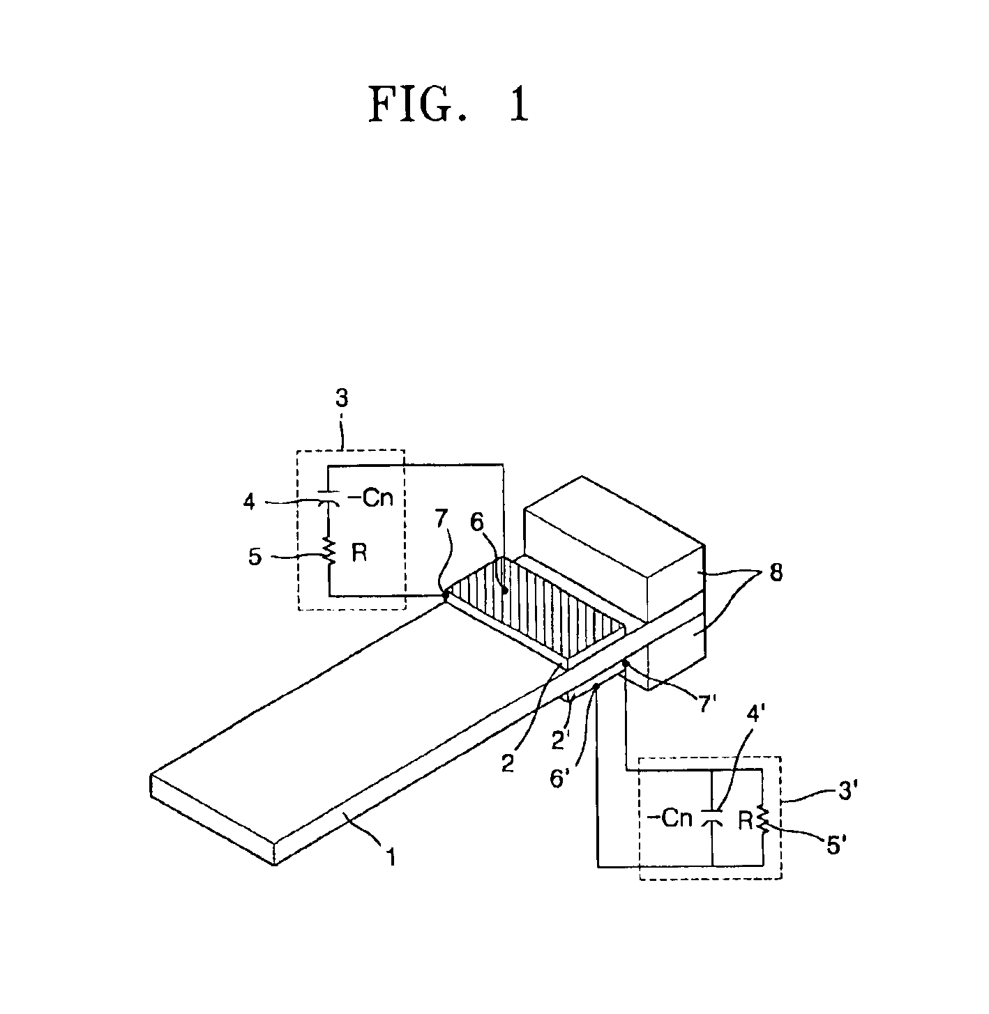
Referring to FIG. 1, the multi-mode vibration damper using the negative capacitance shunt circuits according to the present invention is formed of a beam 1, which generates vibration and / or noise by receiving mechanical energy, such as force, pressure, and stress; an upper piezoelectric material 2, which is attached on the beam 1, for generating electric energy, such as voltage and current, when receiving stress due to the vibration and / or noise, and for transforming its shape when receiving a predetermined electric energy; and a series shunt circuit unit 3, which is connected to two terminals of the upper piezoelectric material 2, for feeding back the electric energy generated by the upper piezoelectric material 2 to the upper piezoelectric material 2 via the shunt impedance to induce the transformati...


PUM


Abstract

A novel multi-mode vibration damper is invented by using a pair of piezoelectric patches connected with negative capacitance shunt circuit units. A piezoelectric material connected with a series resistor-negative capacitor branch circuit is capable of suppressing the vibration and / or noise amplitudes in the low frequency range. The other piezoelectric material connected with a parallel resistor-negative capacitor circuit is for suppressing the vibration and / or noise amplitudes in the high frequency range. By combining two negative capacitance shunt circuit units, a multi-mode vibration damper is capable of suppressing the whole structure modes simultaneously. In order to describe the characteristic behaviors of a multi-mode vibration damper, the stiffness ratio and loss factor with respect to the non-dimensional frequency are considered. The mechanism of a shunt damper is also described as considering a shunt voltage generated by the shunt impedance. The example results show that the multi-mode vibration damper reduces the vibration amplitudes of the vibrating system significantly across a broadband frequency range.

Description

This application claims the priority of Korean Patent Application No. 2002-25397, filed on May 8, 2002 and No. 2002-34881, filed on Jun. 21, 2002 in the Korean Intellectual Property Office, which are incorporated herein in their entirety by reference.FIELD OF THE INVENTIONThe present invention relates to a multi-mode vibration damping device and method to suppress the multimode vibration and / or noise amplitudes by using piezoelectric materials and negative capacitance shunt circuits.BACKGROUND OF INVENTIONVibration suppression via piezoelectric shunt circuits has been of popular interest in recent years due to lightweight, ease of use, and good performance. Among the shunt devices that have been widely used are the resistive and inductive shunt circuits. However, these devices have, so far, been limited to control of a single vibration mode by matching the electrical resonance of the shunting device with the mechanical resonance of the vibrating structure or system.The external term...

Claims


Application Information

Patent Timeline
Patent Type & Authority Patents(United States)
IPC IPC(8): F16F15/00H01L41/00H01L41/04
CPCF16F15/005H01L41/042
Inventor PARK, CHUL-HUE
Owner POHANG UNIV OF SCI & TECH
Why Eureka
Try Eureka