Rotation detecting device

Active Publication Date: 2005-03-22
MITSUBISHI ELECTRIC CORP
View PDF3 Cites 17 Cited by
  • Summary
  • Abstract
  • Description
  • Claims
  • Application Information

AI Technical Summary

Benefits of technology

It is therefore an object of the present invention to provide a rotation detecting device with which it is possible to make the phase difference between two signals used for detecting the rotation direction of a magnetic moving body ¼ of a period and it is possible to increase tolerance with respect to deviations in comparison levels of comparator circuits in a signal processing circuit part and deviations in the outputs of amplifier circuits and perform stable and certain operation.
With this invention it is possible to make the phase difference between two signals used for detecting the rotation direction of the magnetic moving body ¼ of a period, whereby tolerance with respect to deviations in comparison levels of comparator circuits and deviations in outputs of amplifier circuits can be increased and stable and certain operation performed.

Problems solved by technology

The related art rotation detecting device has had the problem that, because it is constructed as described above, when deviations arise in the comparison level Vref1 of the first comparator circuit and the comparison level Vref2 of the second comparator circuit in the signal processing circuit part 3, or when deviations arise in the amplifier circuit outputs, it is not possible for rotation direction detection to be effected accurately.

Method used


Image

  • Rotation detecting device
  • Rotation detecting device
  • Rotation detecting device

Examples


embodiment 1

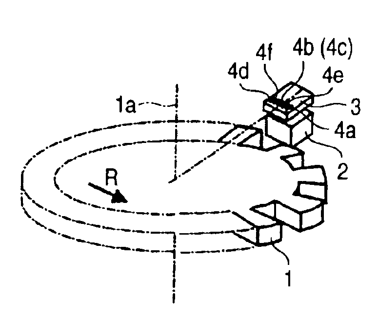
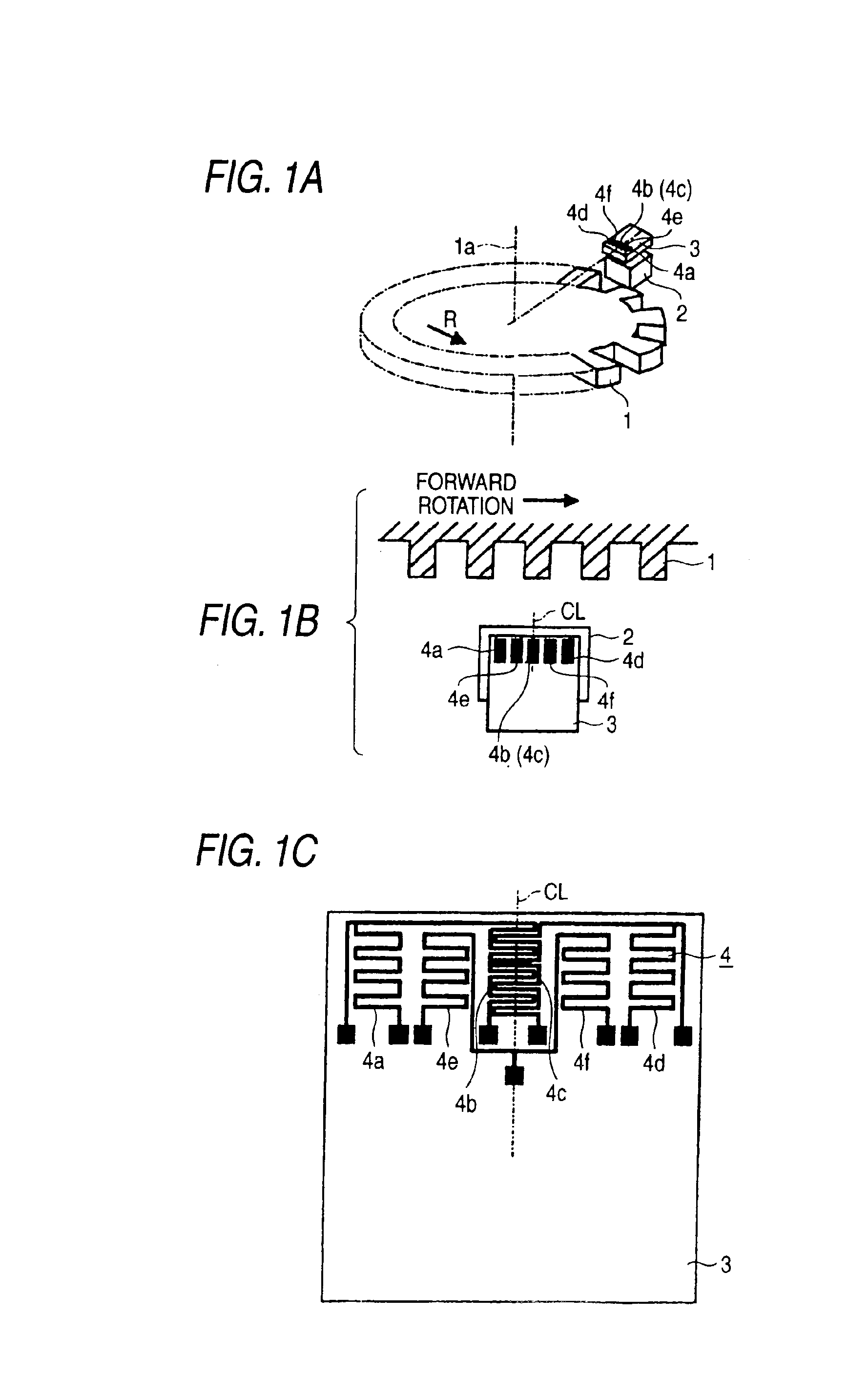
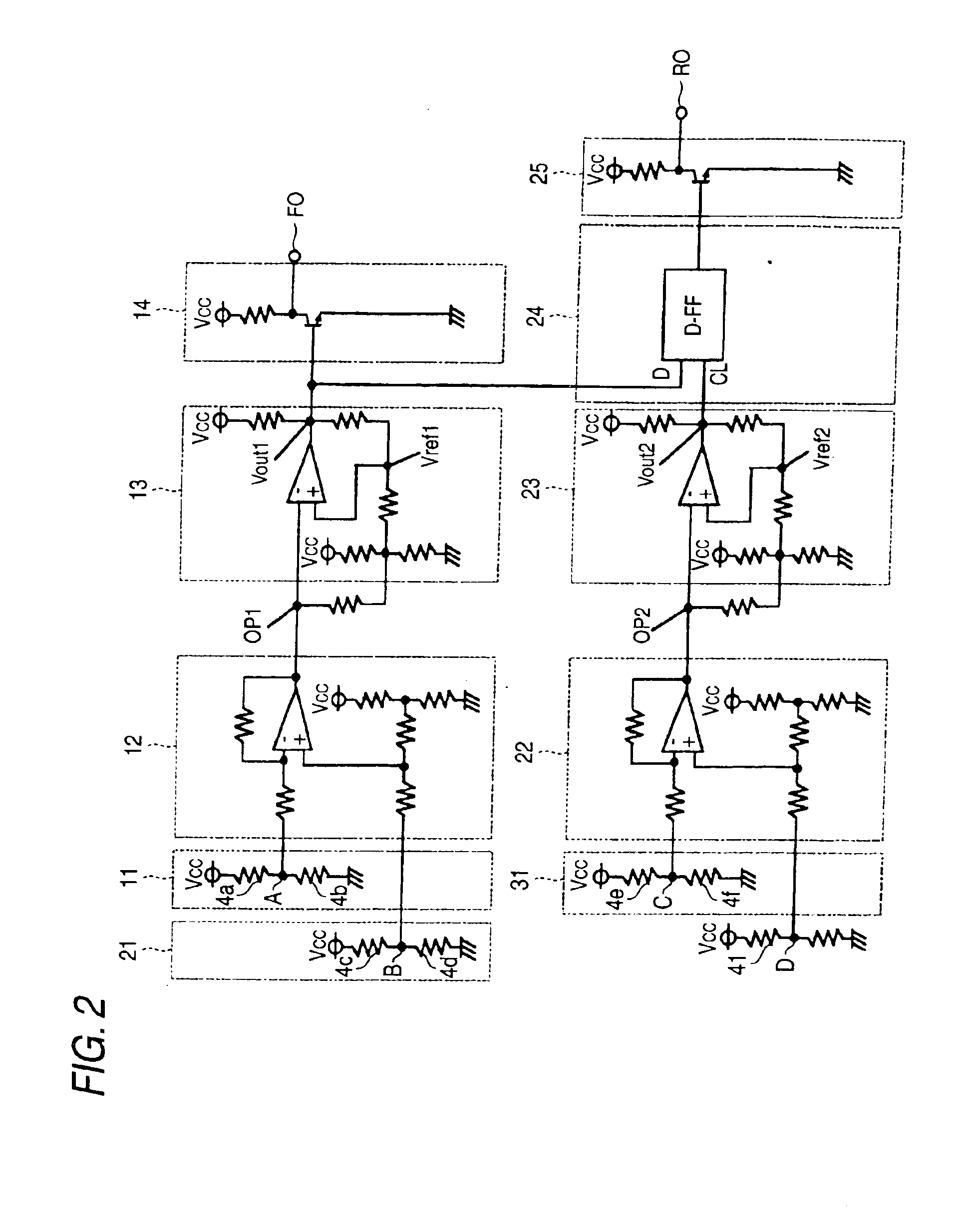
FIGS. 1A through 1C are construction views showing a rotation detecting device of Embodiment 1, FIG. 1A being a perspective view, FIG. 1B a plan view and FIG. 1C a pattern view of magneto-resistance segments. FIG. 2 is a circuit diagram of a signal processing circuit part.

This rotation detecting device has a cogwheel-like magnetic moving body 1 shaped to cause changes in a magnetic field; a magnet 2 disposed facing the magnetic moving body 1 and magnetized in the rotational axis direction 1a of the magnetic moving body 1; and a signal processing circuit part 3 on which is formed a magneto-electric converter device 4 made up of six magneto-resistance segments 4a through 4f at a predetermined pitch in the rotation direction of the magnetic moving body 1.

These six magneto-resistance segments 4a through 4f are formed by film formation on the signal processing circuit part 3, which consists of an IC chip, and are disposed in a predetermined rotation direction of the magnetic moving body ...

embodiment 2

FIG. 9 shows an example of another magnetic circuit construction which can be applied to this invention, in which a magnet 2 is disposed facing a magnetic moving body 1 with its magnetization direction made perpendicular to the rotational axis direction 1a of the magnetic moving body 1, and between the magnet 2 and the magnetic moving body 1 a magneto-electric converter device 4 made up of six magneto-resistance segments 4a through 4f is disposed perpendicular to the magnetization direction of the magnet 2. The pattern of the magneto-resistance segments 4a through 4f can be the same as in Embodiment 1.

With this second preferred embodiment also, the same effects as those of Embodiment 1 can be obtained.

embodiment 3

FIG. 10 shows another example of a pattern of magneto-resistance segments which can be applied to the invention, in which a magneto-electric converter device 4 is made up of six magneto-resistance segments 4a through 4f formed at a predetermined pitch and of these magneto-resistance segments the first and third in a predetermined rotation direction of the magnetic moving body 1 form a first bridge circuit 11 and the fourth and sixth form a second bridge circuit 21 and the second and fifth form a third bridge circuit 31. In this way also, the same effects as those of Embodiment 1 can be obtained.


PUM


Abstract

Six magneto-resistance segments are formed by film-forming on a signal processing circuit part consisting of an IC chip and are disposed in a predetermined rotation direction of a magnetic moving body, symmetrically about the centerline of a magnet perpendicular to that rotation direction. Two pairs of magneto-resistance segments, whose pitch centers are positioned symmetrically with respect to the centerline of the magnet, form first and second bridge circuits, and the remaining pair of magneto-resistance segments, which has its pitch center on the centerline of the magnet, forms a third bridge circuit.

Description

BACKGROUND OF THE INVENTION1. Field of the InventionThis invention relates to a rotation detecting device for sensing a rotation direction using a magneto-electric converter device.2. Description of the Related ArtAs shown in Patent Document 1, a rotation detecting device of related art using a magneto-electric converter device has a magnetic moving body shaped to cause changes in a magnetic field, a magnet disposed facing the magnetic moving body and magnetized in the rotational axis direction of the magnetic moving body, and a processing circuit part with four magneto-resistance segments constructed integrally and disposed with a predetermined spacing in the rotational axis direction of the magnetic moving body. A pair of magneto-resistance segments adjacent in the rotation direction of the magnetic moving body form a first bridge circuit, and another pair of magneto-resistance segments adjacent in the rotation direction of the magnetic moving body form a second bridge circuit.A f...

Claims


Application Information

Patent Timeline
IPC IPC(8): G01B7/30G01P13/02G01D5/22G01D5/12G01P13/04G01D5/14G01D5/16
CPCG01D5/145G01P13/04
Inventor YOKOTANI, MASAHIROSHINJO, IZURUHIRAOKA, NAOKI
Owner MITSUBISHI ELECTRIC CORP
Why Eureka
Try Eureka