Radio device and method of calibration thereof

Inactive Publication Date: 2005-03-22
HERA WIRELESS
View PDF7 Cites 17 Cited by
  • Summary
  • Abstract
  • Description
  • Claims
  • Application Information

AI Technical Summary

Benefits of technology

According to the present invention, as hereinabove described, information related to transmission characteristics of each transmission system is estimated on the basis of a known signal transmitted from each transmission system and a received signal measured therein in a radio apparatus including a plurality of transmission systems, whereby calibration of the transmission characteristics between a receiving circuit and a transmission circuit of each transmission system can be performed in a simple structure at a low cost, without separately providing a specific measuring circuit.

Problems solved by technology

In this case, it follows that the adaptive array radio base station 1 receiving the mixed radio signals from both users A and B in the aforementioned manner outputs the signals from the users A and B in a mixed state unless some necessary processing is performed, to disadvantageously hinder communication with the regular user A.
Even if the adaptive array radio base station 1 completely controls weighting, however, the transmission characteristics of the transmitted signal may change with respect to the received signal such that the transmitted signal cannot be transmitted to the target user.
If the distances are different from each other, a difference in phase rotation quantity, a difference in amplitude fluctuation quantity, or the like is disadvantageously caused between the received signal and the transmitted signal received in and transmitted from each antenna, and the radio signal cannot be transferred between the target user and the adaptive array radio base station 1 with excellent directivity.
In general, a measuring circuit for measuring the transmission characteristics is separately provided on the adaptive array radio base station, to disadvantageously enlarge and complicate the circuit structure of the adaptive array radio base station while increasing the cost.

Method used


Image

  • Radio device and method of calibration thereof
  • Radio device and method of calibration thereof
  • Radio device and method of calibration thereof

Examples


fifth embodiment

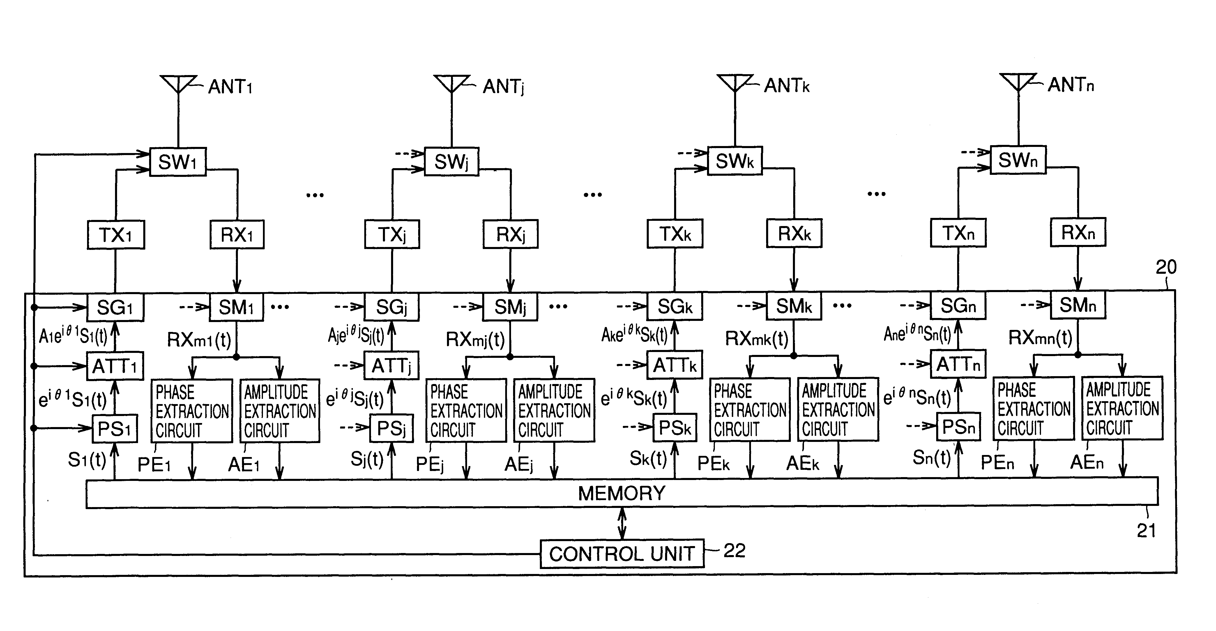
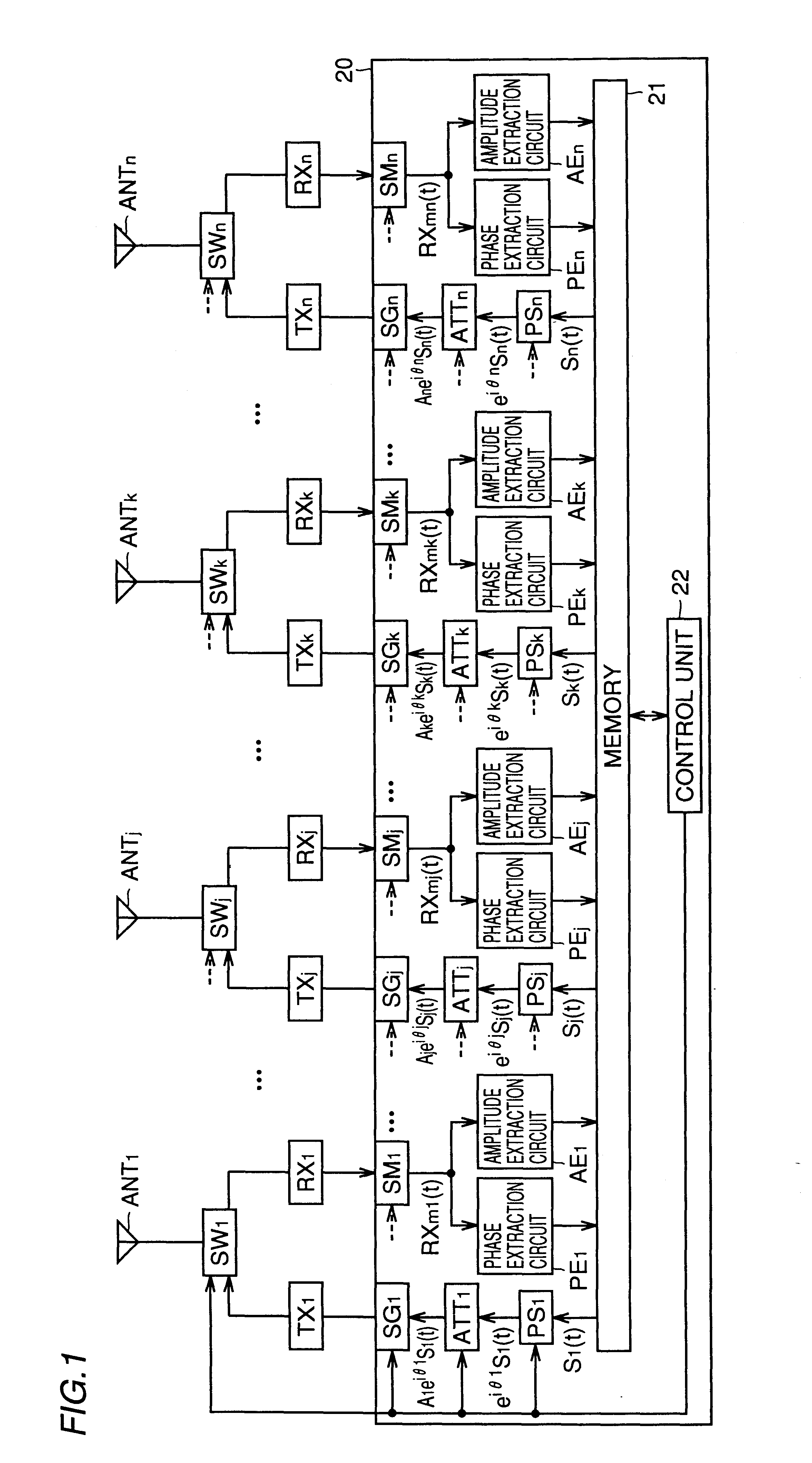
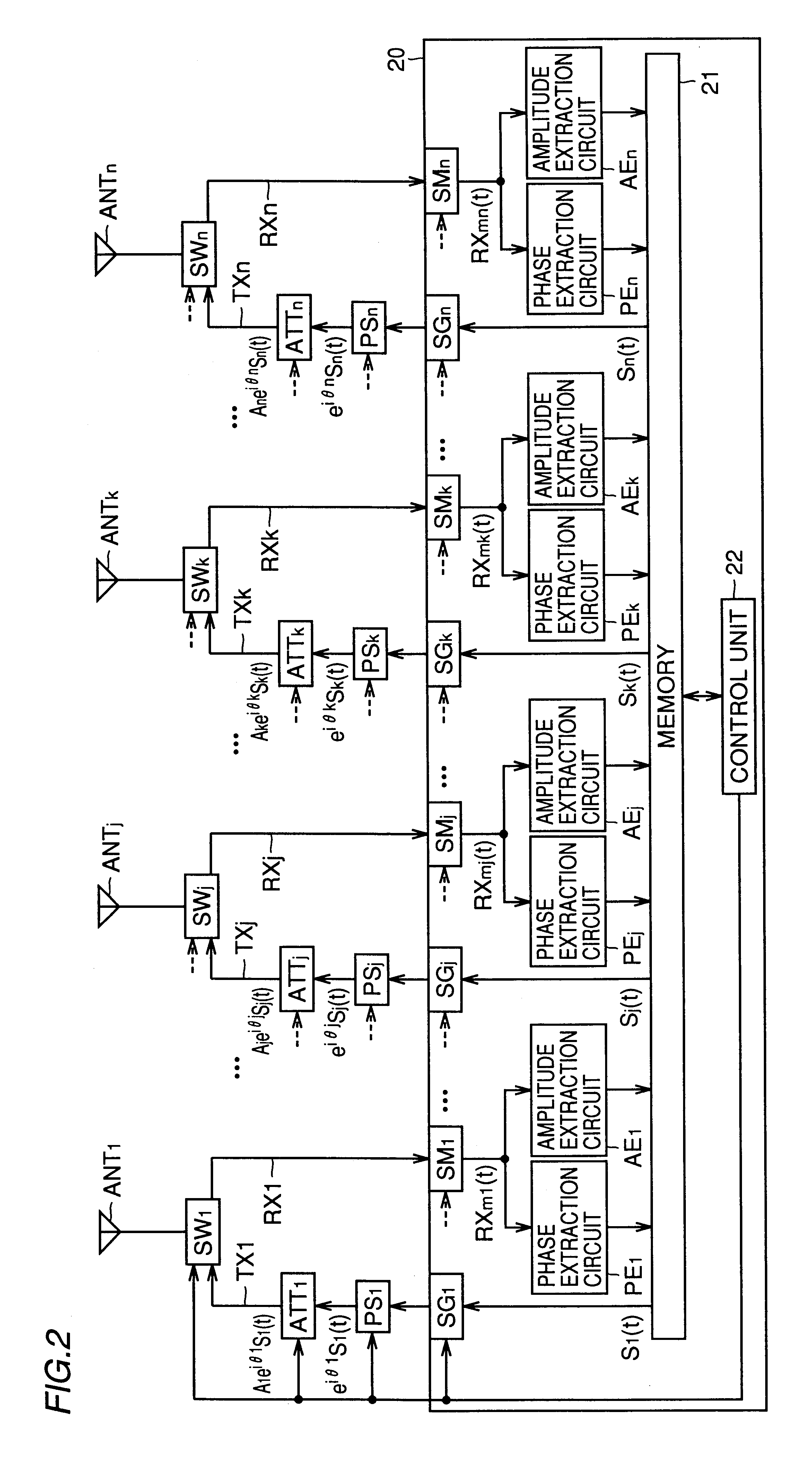
FIG. 34 is a block diagram showing a specific circuit structure according to a fifth embodiment of the present invention. In the fifth embodiment shown in FIG. 34, time averaging circuits are added to the first embodiment of the first structure of the present invention shown in FIG. 15. The operation principle of an adaptive array radio base station according to the fifth embodiment is now described.

In calibration, a phase rotation quantity θj of a phase shifter PSj of a j-th (j=1, 2, . . . , n) transmission system is set to 0 and an amplitude fluctuation quantity Aj of an attenuator ATTj is set to 1 (=0 dB). A known signal Sj(t) corresponding to the j-th transmission system is read from a memory 21 and transmitted through an antenna element ANTj.

The transmitted signal is received in antenna elements ANTk (k=1, 2, . . . , n, where j≠k) of all transmission systems excluding the j-th transmission system, and measured by a received signal measuring unit SMk of each transmission system ...

sixth and seventh embodiments

FIG. 37 is a block diagram showing a specific circuit structure of a sixth embodiment of the present invention. In the sixth embodiment shown in FIG. 37, time averaging circuits are added to positions different from those in the fifth embodiment shown in FIG. 34 in the first embodiment of the first basic structure of the present invention shown in FIG. 15.

Both sides of the above equation (1-2) are divided by a known signal Sj(t) for calculating natural logarithms and performing Taylor expansion without time averaging, dissimilarly to the fifth embodiment. When the S-N ratio is not much excellent, the result of Taylor expansion is expressed in the following approximation (2-8).

When separately extracting imaginary parts and real parts on both sides of the equation (2-8) and performing time averaging, the term including a noise component njk(t) on the left side reaches 0 while the remaining terms are constant with respect to time, and hence the following equations (2-9) and (2-10) are ...

eighth and ninth embodiments

FIG. 42 is a block diagram showing a specific circuit structure of an eighth embodiment of the present invention. The eighth embodiment shown in FIG. 42 is different from the sixth embodiment shown in FIG. 37 merely in a point that division by a known signal Sj(t) is performed not on a measured received signal RXj(t) but on a received signal subjected to calculation of the natural logarithm, separated into imaginary and real parts and time-averaged in a final stage.

FIG. 43 is a block diagram showing a specific circuit structure of a ninth embodiment of the present invention. The ninth embodiment shown in FIG. 43 is different from the seventh embodiment shown in FIG. 38 merely in a point that division by a known signal Sj(t) is performed not on a measured received signal RXj(t) but on a received signal subjected to calculation of the natural logarithm, time-averaged and separated into imaginary and real parts in a final stage.

The flow chart of FIG. 39 also inclusively shows operation...


PUM


Abstract

An adaptive array radio base station comprises at least three antenna elements (ANTj (j=1, 2, . . . , n)) and a signal processing circuit (20). In calibration, the difference in a phase rotation quantity and the difference in an amplitude fluctuation quantity between a transmission circuit and a receiving circuit in each transmission system are estimated on the basis of a known signal transmitted from each transmission system and a received signal measured in each transmission system. A phase rotation quantity of a phase shifter (PSj) and an amplitude fluctuation quantity of an attenuator (ATTj) are set on the basis of the results of the estimation. Thus provided are a radio apparatus and a calibration method capable of calibrating transmission characteristics of the transmission circuit and the receiving circuit in a simple structure at a low cost without providing a specific measuring circuit.

Description

TECHNICAL FIELDThe present invention relates to a radio apparatus and a calibration method therefor, and more particularly, it relates to a radio apparatus employed in an adaptive array radio base station and a calibration method therefor.BACKGROUND ARTAn adaptive array radio base station employing an array antenna is recently put into practice as a radio base station for a mobile communication system such as a portable telephone. The operation principle of such an adaptive array radio base station is described in the following literature, for example:B. Widrow, et al.: “Adaptive Antenna Systems”, Proc. IEEE, vol.55, No.12, pp.2143-2159 (December 1967).S. P. Applebaum: “Adaptive Arrays”, IEEE Trans. Antennas & Propag, vol.AP-24, No.5, pp.585-598 (September 1976).O. L. Frost, III: “Adaptive Least Squares Optimization Subject to Linear Equality Constraints”, SEL-70-055, Technical Report, No.6796-2, Information System Lab., Stanford Univ. (August 1970).B. Widrow and S. D. Stearns: “Ada...

Claims


Application Information

Patent Timeline
IPC IPC(8): H01Q3/26H04B7/04H04B17/00H04B17/19H04B17/29H04W16/28H04W24/02H04W24/06H04W88/08
CPCH01Q3/2605H04B17/12H04B7/04H01Q3/267H01Q21/00
Inventor DOI, YOSHIHARUIINUMA, TOSHINORI
Owner HERA WIRELESS
Why Eureka
Try Eureka