
Compact neutron generator

a generator and compact technology, applied in the field of compact generators, can solve the problems of limited neutron production, limited neutron yield, and limited ion source performance and beam size,

Inactive Publication Date: 2005-03-22
RGT UNIV OF CALIFORNIA
View PDF8 Cites 37 Cited by
  • Summary
  • Abstract
  • Description
  • Claims
  • Application Information

AI Technical Summary

Benefits of technology

[0020]The neutron generator is nearly a point source. The beam can be pulsed rapidly to achieve ultrashort neutron bursts. To achieve a desired neutron flux, the total beam power deposited on the target may be too high to cool merely with running water. The target may be moved rapidly up and down so that the average power deposited on the surface of the target may be kept at a reasonable level.

Problems solved by technology

Neutron yield is limited by the ion source performance and beam size.
The production of neutrons is limited by the beam current and power deposition on the target.
In the conventional neutron tube, the extraction aperture and the target are limited to small areas, and so is the neutron output flux.
The deuterium-on-deuterium (D-D) reaction, with a cross section for production a hundred times lower, has not been able to provide sufficient neutron flux.
Detecting such materials hidden in baggage or cargo is challenging under real-world conditions.
The first-generation TNA screeners were too large, complex, and expensive; furthermore, TNA requires moderators to slow fast neutrons from a source to thermal neutrons.
A D-D source is unsuitable because it is too low energy.
While a D-T source may be used, it produces too high energy neutrons which must be slowed by moderators to the desired energy range, resulting is larger sized systems with large loss of neutron flux and loss of beam directionality.
The system is low current, large and complex.
However, this reaction has not been used in conventional neutron sources.

Method used


Image

  • Compact neutron generator
  • Compact neutron generator
  • Compact neutron generator

Examples


Embodiment Construction

ass="d_n">[0025]FIGS. 4A, B are perspective views, partly in section, of the two alternate basic embodiments of the cylindrical neutron generator.

[0026]FIGS. 5A, B, C are further perspective views, partly in section, of the two alternate basic embodiments of the cylindrical neutron generator.

[0027]FIGS. 6A, B are a perspective view, partly in section, and a radial cross section of a nested coaxial neutron source.

[0028]FIGS. 6C, D are radial and axial cross sections of the nested neutron source showing the alternating targets and plasma generating regions with cooling system.

[0029]FIGS. 6E, F are radial and axial cross sections of the nested neutron source showing the alternating targets and plasma generating regions with the RF antennas.

[0030]FIG. 7 is a perspective view, partly in section, of a spherical neutron generator.

[0031]FIGS. 8A, B are side and top cross sectional views of a preferred neutron generator according to the invention.

DETAILED DESCRIPTION OF THE INVENTION

[0032]Th...


PUM


Abstract

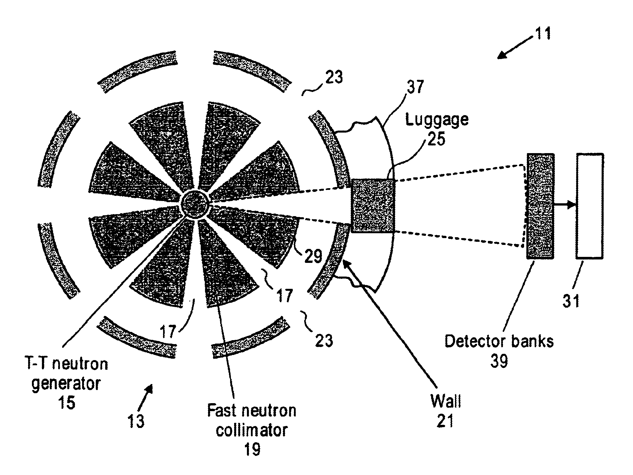
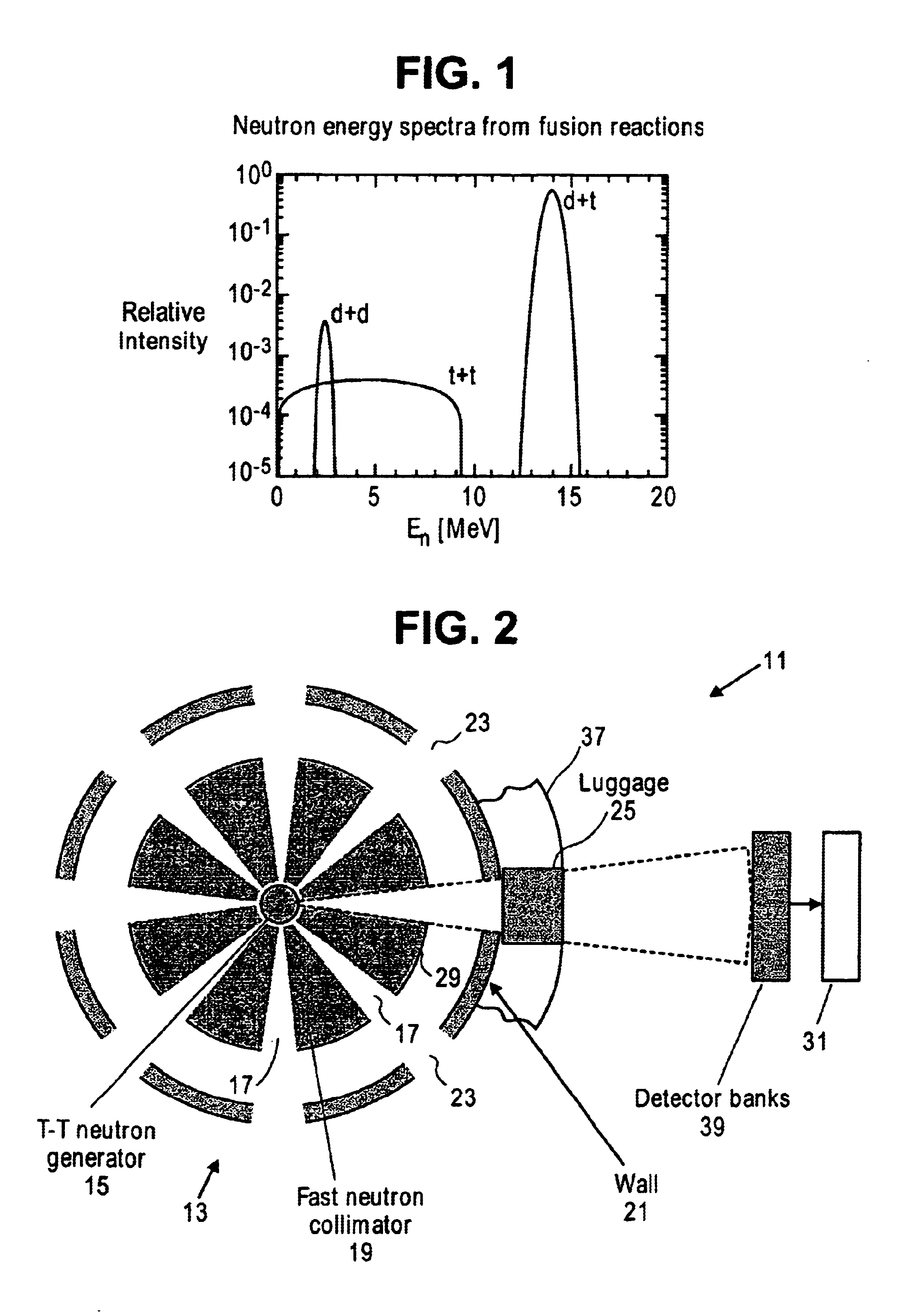
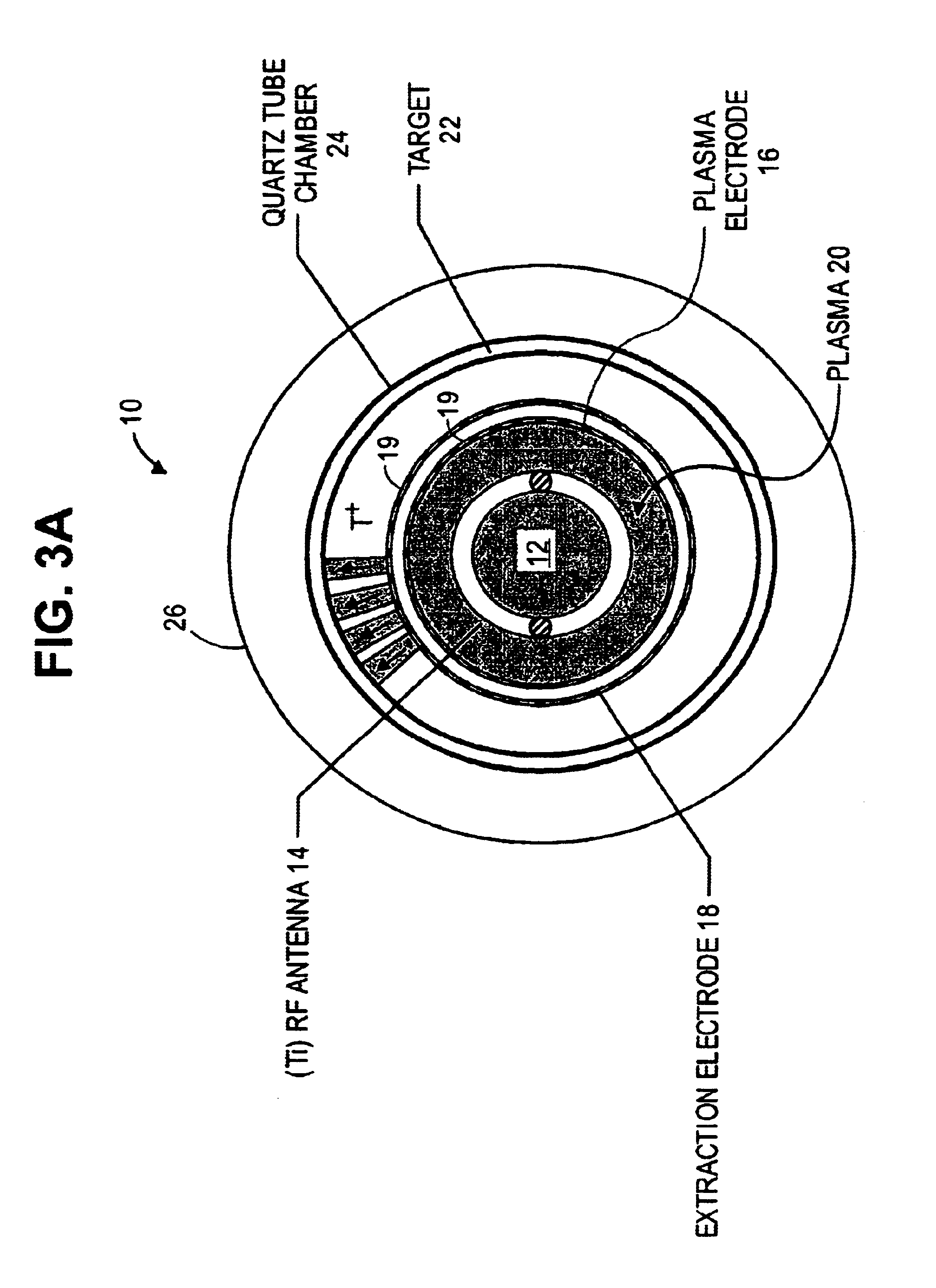
A compact neutron generator has at its outer circumference a toroidal shaped plasma chamber in which a tritium (or other) plasma is generated. A RF antenna is wrapped around the plasma chamber. A plurality of tritium ion beamlets are extracted through spaced extraction apertures of a plasma electrode on the inner surface of the toroidal plasma chamber and directed inwardly toward the center of neutron generator. The beamlets pass through spaced acceleration and focusing electrodes to a neutron generating target at the center of neutron generator. The target is typically made of titanium tubing. Water is flowed through the tubing for cooling. The beam can be pulsed rapidly to achieve ultrashort neutron bursts. The target may be moved rapidly up and down so that the average power deposited on the surface of the target may be kept at a reasonable level. The neutron generator can produce fast neutrons from a T-T reaction which can be used for luggage and cargo interrogation applications. A luggage or cargo inspection system has a pulsed T-T neutron generator or source at the center, surrounded by associated gamma detectors and other components for identifying explosives or other contraband.

Description

RELATED APPLICATIONS[0002]This application claims priority of Provisional Application Ser. No. 60 / 370,948 filed Apr. 8, 2002, which is herein incorporated by reference.GOVERNMENT RIGHTS[0003]The United States Government has rights in this invention pursuant to Contract No. DE-AC03-76SF00098 between the United States Department of Energy and the University of California.BACKGROUND OF THE INVENTION[0004]Conventional neutron tubes employ a Penning ion source and a single gap extractor. The target is a deuterium or tritium chemical embedded in a molybdenum or tungsten substrate. Neutron yield is limited by the ion source performance and beam size. The production of neutrons is limited by the beam current and power deposition on the target. In the conventional neutron tube, the extraction aperture and the target are limited to small areas, and so is the neutron output flux.[0005]Commercial neutron tubes have used the impact of deuterium on tritium (D-T) for neutron production. The D-T re...

Claims


Application Information

Patent Timeline
IPC IPC(8): H05H3/00H05H3/06
CPCH05H3/06Y02E30/10
Inventor LEUNG, KA-NGOLOU, TAK PUI
Owner RGT UNIV OF CALIFORNIA
Learn More