Movable aerodynamic surface for an aircraft

a technology of aerodynamic surface and aircraft, which is applied in the direction of aircraft control, instruments, transportation and packaging, etc., can solve the problems of unsatisfactory broadband noise, and unsatisfactory tonal and broadband nois

Pending Publication Date: 2022-09-29
AIRBUS OPERATIONS GMBH
View PDF0 Cites 0 Cited by
  • Summary
  • Abstract
  • Description
  • Claims
  • Application Information

AI Technical Summary

Problems solved by technology

The noise is usually generated by sharp lateral edges of the first and second skin portions upstream from the inboard and / or outboard cavity which cause vortices that in turn are responsible for an undesired broadband noise.
Additionally, the noise is generated by resonance within the inboard and / or outboard cavity which acts as a Helmholtz resonator that may cause undesired tonal and broadband noise.
However, partial broadband noise still remained as the sharp lateral edges of the first and second skin portions upstream the cavities were still present.
However, the foam filler elements are difficult to produce, install and maintain at a small scale or complex shape, such as in the area of the leading edge or the trailing edge of the aerodynamic surface.

Method used


Image

  • Movable aerodynamic surface for an aircraft
  • Movable aerodynamic surface for an aircraft
  • Movable aerodynamic surface for an aircraft

Examples


Embodiment Construction

[0030]Some embodiments will now be described with reference to the Figures.

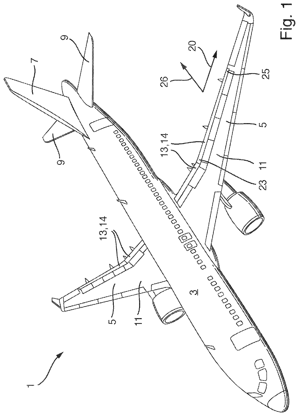
[0031]In FIG. 1 an aircraft 1 according to the invention is illustrated. The aircraft 1 has a fuselage 3, wings 5, a vertical tail plane 7 and a horizontal tail plane 9. Each wing 5 comprises a main wing ii and at least one movable aerodynamic surface 13 in the form of a high lift flap 14 mounted to the trailing edge of the main wing 5 movably between a retracted position and an extended position.

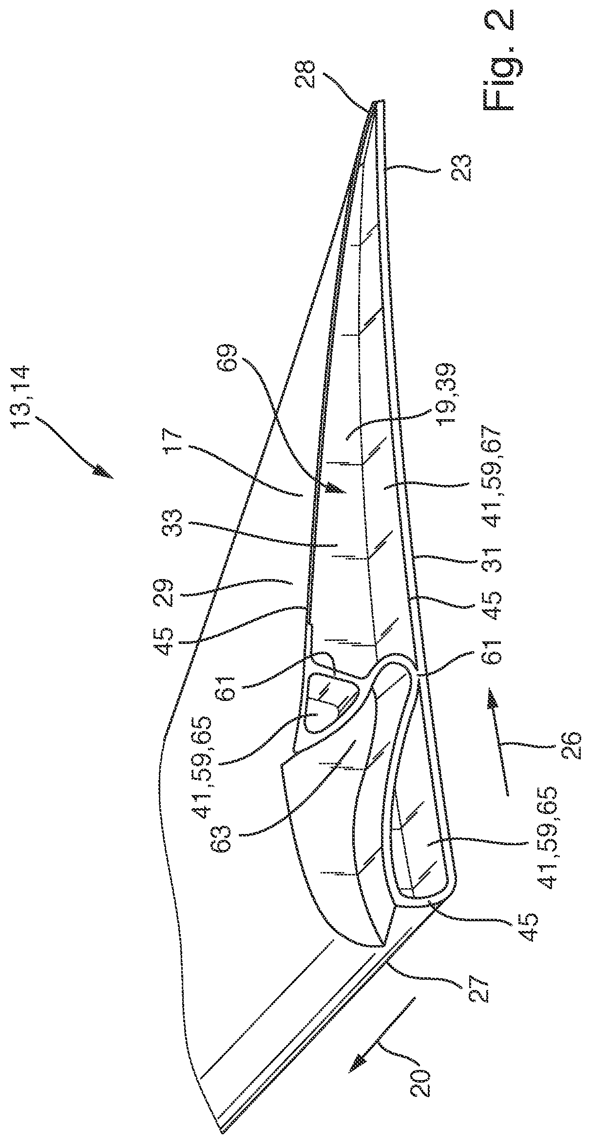
[0032]As shown in FIG. 2, the aerodynamic surface 13 comprises a skin 17, a stiffener arrangement 19, and an acoustic filler arrangement 21. The skin 17 extends in a span direction 20 from an inboard end 23 to an outboard end 25 and extends in a chord direction 26 from a leading edge 27 to a trailing edge 28. The skin 17 includes an upper, first skin portion 29 and a lower, second skin portion 31. Both first and second skin portions 29, 31 extend from the leading edge 27 to the trailing edge 28 and together surround ...


PUM


Abstract

A movable aerodynamic surface for an aircraft is disclosed including a skin having a first skin portion and a second skin portion both extending from the leading edge to the trailing edge and together surrounding an interior from opposite sides, and a stiffener arrangement arranged in the interior and including at least an inboard stiffener in the area of the inboard end and/or an outboard stiffener in the area of the outboard end. At the inboard end between the first skin portion, the second skin portion and the inboard stiffener an inboard cavity is formed, and/or at the outboard end between the first skin portion, the second skin portion and the outboard stiffener an outboard cavity is formed. An acoustic filler arrangement including multiple filler elements is arranged within the inboard cavity and/or the outboard cavity for reducing noise.

Description

CROSS REFERENCE TO RELATED APPLICATION[0001]This application claims priority to and incorporates by reference German Application Number DE 10 2021 107 280.8, filed Mar. 23, 2021.BACKGROUND1. Field of the Invention[0002]The present invention relates to a movable aerodynamic surface for an aircraft, configured for noise reduction, in particular a high lift surface, such as a flap or a slat, or a control surface, such as an aileron, a rudder or an elevator. Further aspects of the invention relate to a wing comprising such an aerodynamic surface, and to an aircraft comprising such an aerodynamic surface and / or such a wing.2. Description of Related Art[0003]The aerodynamic surface comprises a skin, a stiffener arrangement, and an acoustic filler arrangement. The skin extends in a span direction from an inboard end to an outboard end and extends in a chord direction from a leading edge to a trailing edge. The skin includes a first skin portion, preferably an upper skin portion, and a seco...

Claims


Application Information

Patent Timeline
Patent Type & Authority Applications(United States)
IPC IPC(8): B64C1/40B64C3/26
CPCB64C1/40B64C3/26B64C2230/14B64C2230/22B64C9/00B64C9/16G10K11/172B64C2009/005B64C7/00B64C9/18
Inventor BÜSCHER, ALEXANDER
Owner AIRBUS OPERATIONS GMBH
Why Eureka
Try Eureka