Method and apparatus to decrease gas turbine engine combustor emissions

a gas turbine and combustible technology, applied in the ignition of turbine/propulsion engines, engine starters, lighting and heating apparatus, etc., can solve problems such as adversely affecting nox emissions

Inactive Publication Date: 2005-03-29
GENERAL ELECTRIC CO
View PDF22 Cites 68 Cited by
  • Summary
  • Abstract
  • Description
  • Claims
  • Application Information

AI Technical Summary

Benefits of technology

In one aspect, a method for operating a gas turbine engine including a combustor is provided. The combustor includes at least one premixer assembly, a dome plate, and heat shield assemblies. The method comprises discharging...

Problems solved by technology

However, because the spent impingement cooling air is channeled downstream from the mixer assembly, the spent coolin...

Method used


Image

  • Method and apparatus to decrease gas turbine engine combustor emissions
  • Method and apparatus to decrease gas turbine engine combustor emissions
  • Method and apparatus to decrease gas turbine engine combustor emissions

Examples


Embodiment Construction

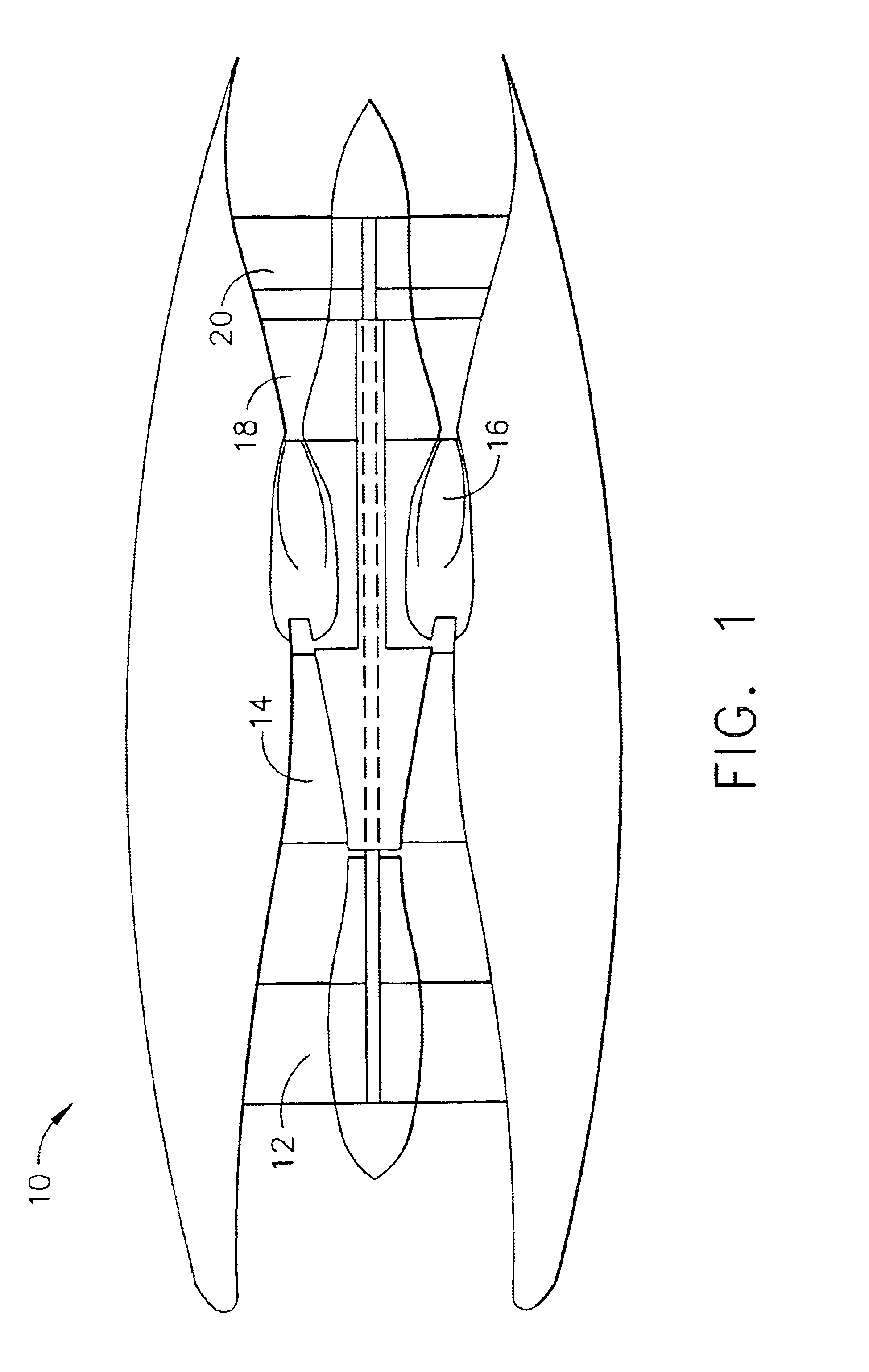
FIG. 1 is a schematic illustration of a gas turbine engine 10 including a low pressure compressor 12, a high pressure compressor 14, and a combustor 16. Engine 10 also includes a high pressure turbine 18 and a low pressure turbine 20.

In operation, air flows through low pressure compressor 12 and compressed air is supplied from low pressure compressor 12 to high pressure compressor 14. The highly compressed air is delivered to combustor 16. Airflow (not shown in FIG. 1) from combustor 16 drives turbines 18 and 20. In one embodiment, gas turbine engine 10 is a CFM engine available from CFM International. In another embodiment, gas turbine engine 10 is an LM6000 DLE engine available from General Electric Company, Cincinnati, Ohio.

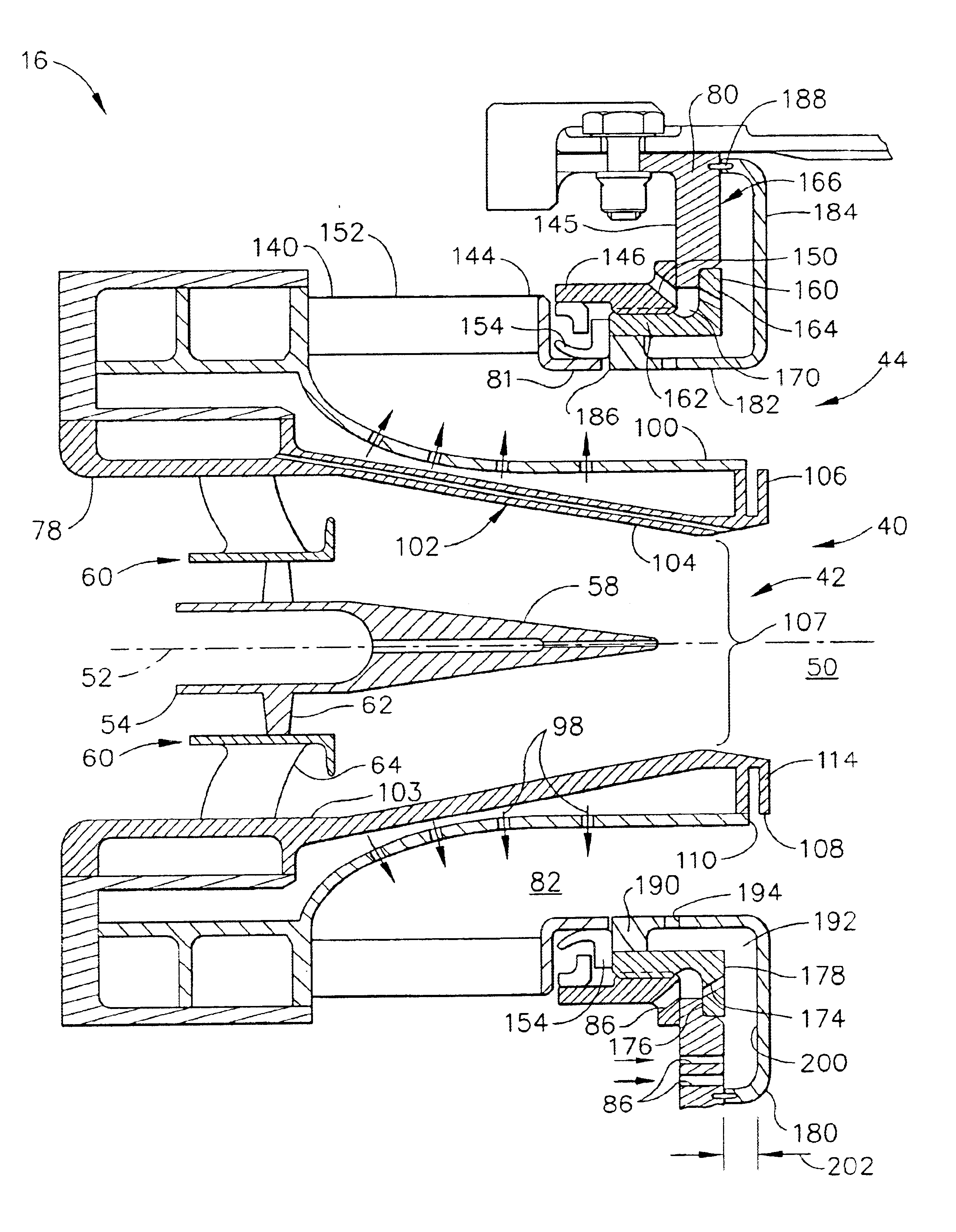
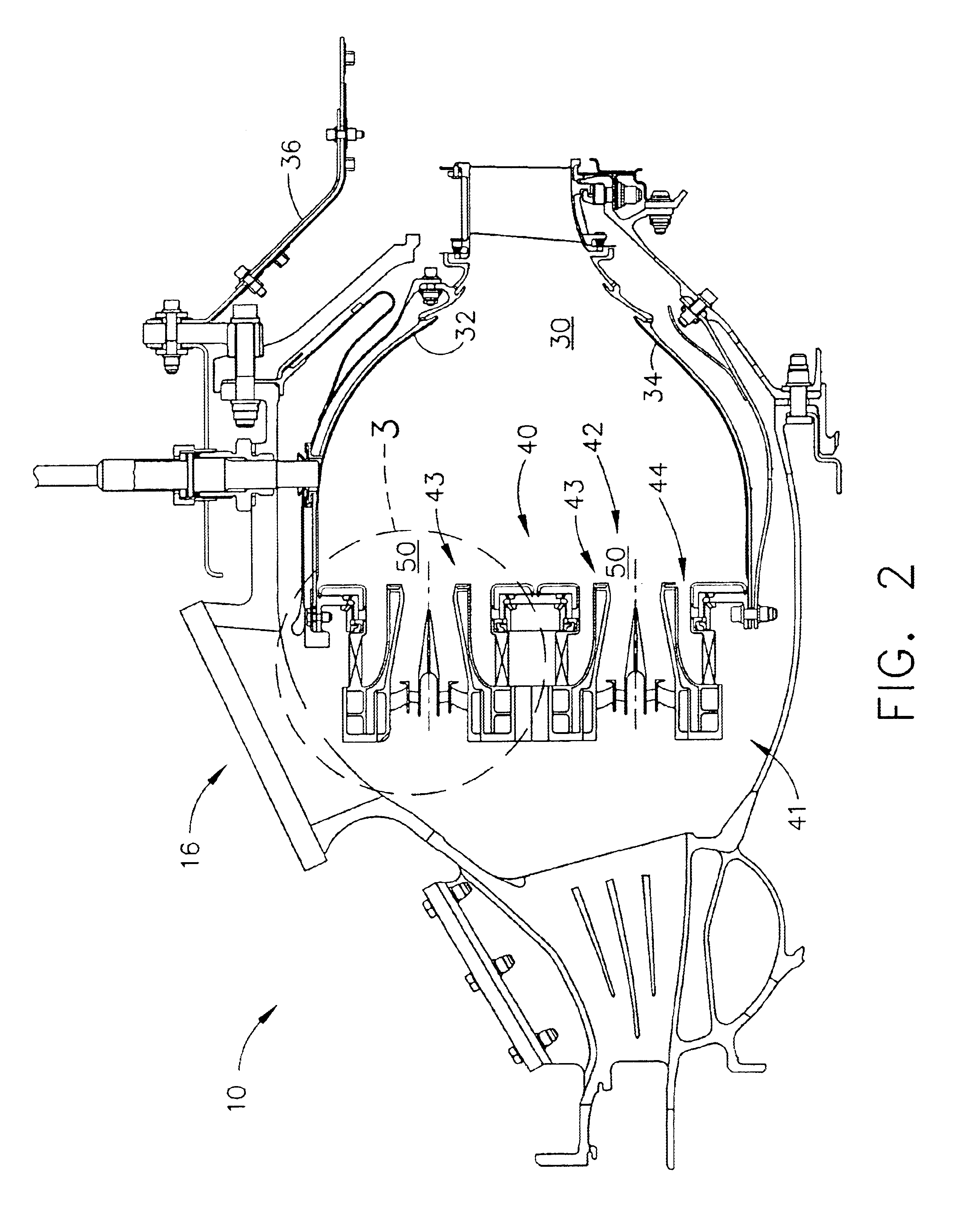
FIG. 2 is a cross-sectional view of combustor 16 for use with a gas turbine engine, similar to engine 10 shown in FIG. 1, and FIG. 3 is an enlarged partial view of combustor 16 taken along area 3. Combustor 16 includes a combustion zone or chamber 30 defined b...


PUM


Abstract

A method enables a gas turbine engine including a combustor to be operated. The combustor includes a mixer assembly including an air swirler, a premixer, a dome plate, and a heat shield. The method comprises discharging fluids from the air swirler into the premixer, and directing cooling fluids through a cooling opening defined in at least one of the swirler and the dome plate towards an upstream side of the heat shield for impingement cooling of the heat shield.

Description

BACKGROUND OF THE INVENTIONThis application relates generally to combustors and, more particularly, to gas turbine combustors.Air pollution concerns worldwide have led to stricter emissions standards both domestically and internationally. Pollutant emissions from industrial aero engines are subject to Environmental Protection Agency (EPA) standards that regulate the emission of oxides of nitrogen (NOx), unburned hydrocarbons (HC), and carbon monoxide (CO). In general, engine emissions fall into two classes: those formed because of high flame temperatures (NOx), and those formed because of low flame temperatures that do not allow the fuel-air reaction to proceed to completion (HC & CO).At least some known gas turbine combustors include between 10 and 30 mixers, which mix high velocity air with liquid fuels, such as diesel fuel, or gaseous fuels, such as natural gas. These mixers usually consist of a single fuel injector located at a center of a swirler for swirling the incoming air t...

Claims


Application Information

Patent Timeline
IPC IPC(8): F23R3/14F23R3/28F23R3/04F23R3/00F23R3/18
CPCF23R3/002F23R3/14F23R3/286Y02T50/675F23R2900/03044Y02T50/60
Inventor BIBLER, JOHN D.HELD, TIMOTHY J.MUELLER, MARK A.
Owner GENERAL ELECTRIC CO
Why Eureka
Try Eureka