Throttle valve adjustment unit

a technology of valve valve and adjustment unit, which is applied in the direction of lifting valve, structural/machine measurement, instruments, etc., can solve the problem of only achieving centering, and achieve the effect of reducing labor intensity and being easy to assembl

Inactive Publication Date: 2005-03-29
PIERBURG GMBH & CO KG NEUSS
View PDF16 Cites 2 Cited by
  • Summary
  • Abstract
  • Description
  • Claims
  • Application Information

AI Technical Summary

Benefits of technology

In short, the objects of the present invention are solved in that the servomotor has a front portion formed as an end shield for a drive shaft of the servomotor and oriented toward the throttle flap end cap. This front portion serves to center the servomotor with respect to the throttle flap end cap and also to center the servomotor in the cover. In this way, it is achieved that the drive shaft of the servomotor precisely engages the drive, and, at the same time, the cover can be brought onto the throttle flap end cap with a precise fit. The servomotor is thereby easily positioned in the cover by means of connection elements, such as, for example, screws, rivets, etc. In order to provide adjustment of the sensor unit in a simple manner on the open throttle flap end cap, it can be provided that the sensor unit be positioned on the throttle flap end cap, whereby the end shield of the servomotors is provided with contact elements that are connected to corresponding contact counterparts on the throttle flap end cap by means of a rigid connection such as by soldering, welding, gluing, etc. In this manner, a secure thermal and vibration insensitive electrical connection is achieved between the servomotor and the sensor unit. It is particularly advantageous, if the contact elements and / or the contact counterparts are friction fit in a shaft and elastically deformed in their axial positioning by the final assembly of the cover with the throttle flap end cap.

Problems solved by technology

Such a centering can only be achieved with difficulty in the prior throttle flap adjustment unit and requires difficult assembly.

Method used


Image

  • Throttle valve adjustment unit
  • Throttle valve adjustment unit
  • Throttle valve adjustment unit

Examples


Embodiment Construction

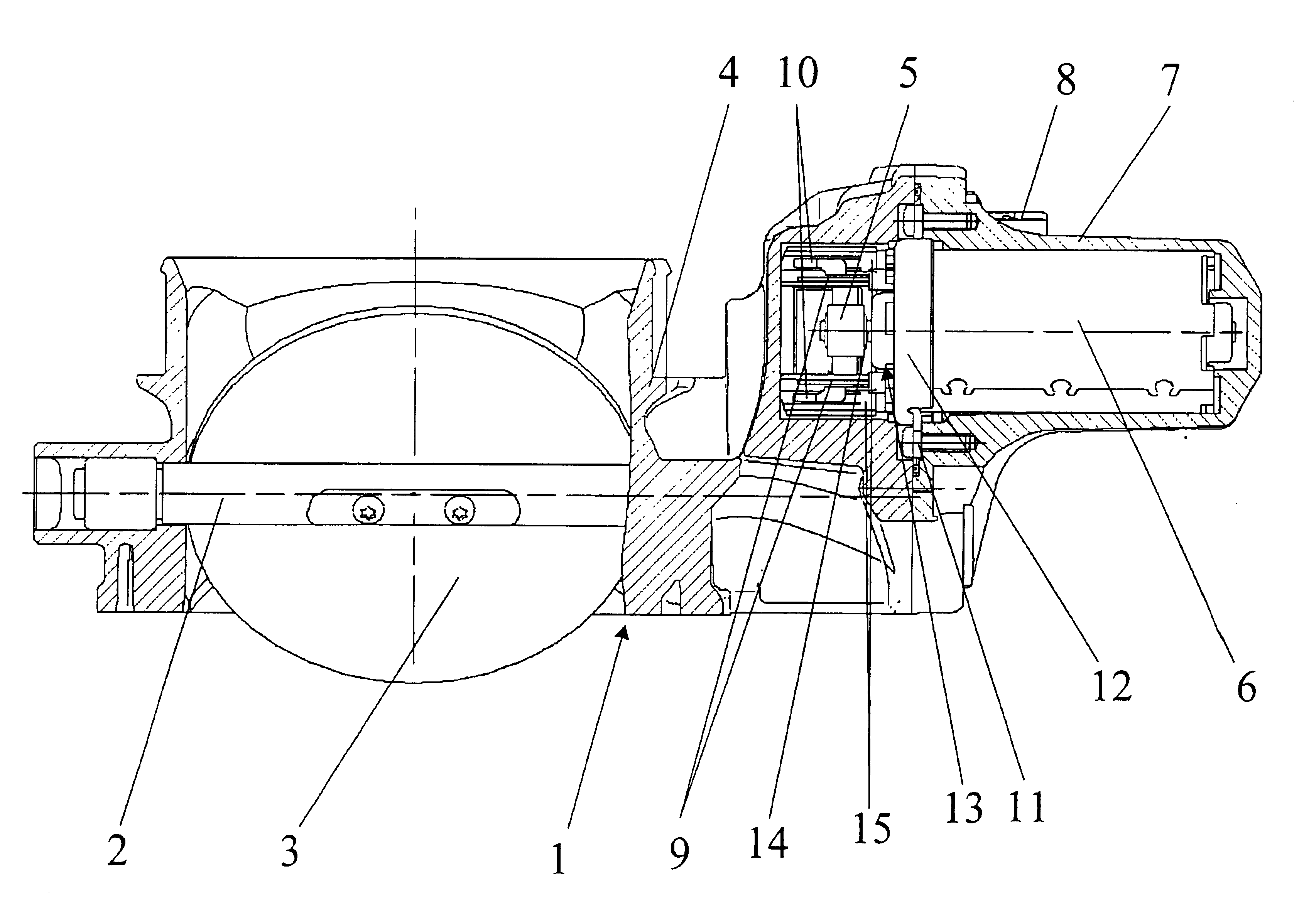
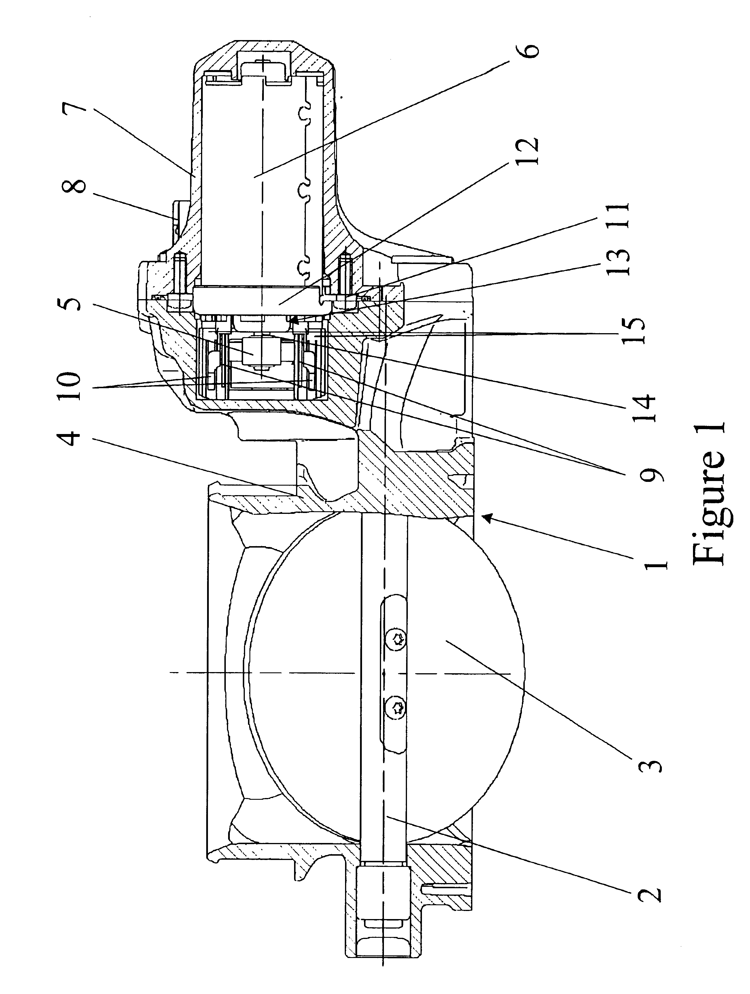
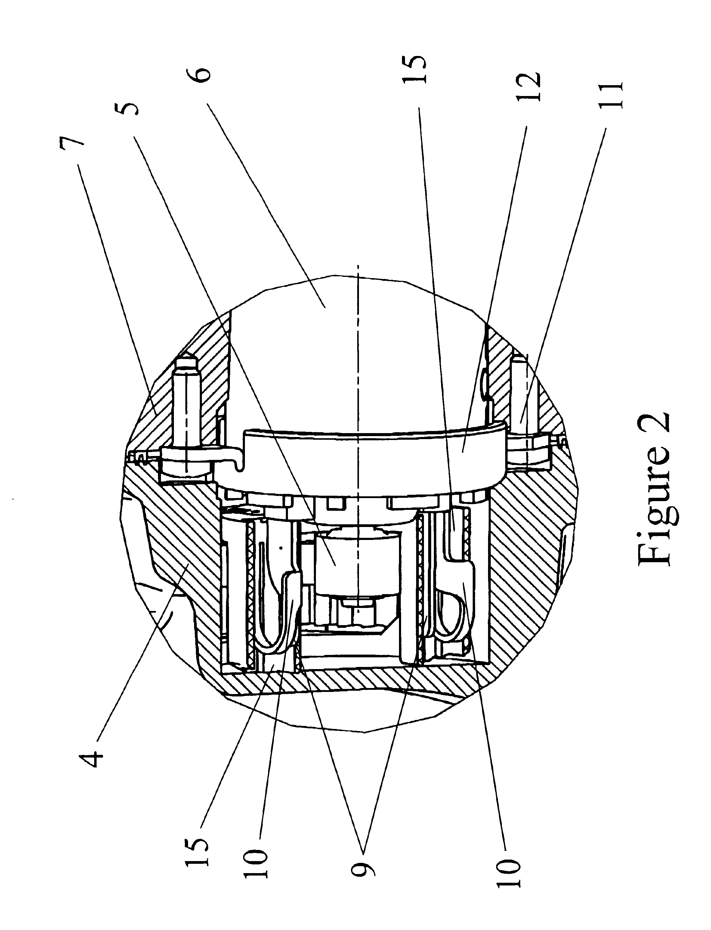
FIG. 1 shows a sectional view of a throttle flap adjustment unit 1 according to the present invention. The throttle flap adjustment unit has a throttle flap 3 fastened to a throttle flap shaft 2, wherein the throttle flap shaft 2 is rotatably journaled in a throttle flap end cap 4. In order to adjust the throttle flap shaft 2, it is connected to a servomotor 6 in a known manner by a drive, for example a gear drive, of which only a pinion 5 is shown. The servomotor 6 is arranged on a cover 7 to be fastened to the throttle flap end cap 4, and is controlled by a motor control device (not shown) to which it is connected by, for example, an electrical coupling element 8. Furthermore, the throttle flap adjustment unit 1 comprises, in a known manner, a sensor unit for determining the position of the throttle flap shaft 2, so that the position can be transmitted to the motor control device to allow, in this manner, precise control of the servomotor 6.

The sensor unit, a potentiometer, for ex...


PUM


Abstract

A throttle flap adjustment unit having a throttle flap fastened to a throttle flap shaft. The throttle flap shaft is rotatably journaled in a throttle flap end pipe. A servomotor is provided for adjusting the throttle flap shaft and is connected to the throttle flap shaft by a drive. A sensor unit is provided for determining a position of the throttle flap shaft. A cover is provided to be fastened onto the throttle flap end pipe, wherein the servomotor is positioned in the cover and controllable over an electrical coupling element, wherein the servomotor (6) has a front portion (12) oriented toward the throttle flap end pipe and formed as an end plate (13) for the drive shaft of the servomotor. The end plate (13) also serves to center the servomotor (6) with respect to the throttle flap end pipe (4) and also to center the servomotor (6) in the cover (7).

Description

FIELD OF THE INVENTIONThe invention relates to a throttle valve adjustment unit, having a throttle flap fastened to a throttle flap shaft, wherein the throttle flap shaft is rotatably journaled in a throttle flap end cap, having a servomotor for adjusting the throttle flap shaft and connected to the throttle flap shaft by a drive, having a sensor unit for determining the adjustment position of the throttle flap shaft, and having a cover fastened to the throttle flap end cap, wherein the servomotor is provided with a cover and is controllable by an electric coupling element.BACKGROUND OF THE INVENTIONOne throttle flap adjustment unit is known from DE-A1-4142810. In this unit, the servomotor is premounted on the cover to be put on the throttle flap end cap. A precisely centered positioning of the cover on the throttle flap end cap is necessary for engagement of a drive shaft of the servomotor with the drive. Such a centering can only be achieved with difficulty in the prior throttle f...

Claims


Application Information

Patent Timeline
Patent Type & Authority Patents(United States)
IPC IPC(8): G01M19/00G01M99/00
CPCF02D9/105F02D11/106F16K27/0218F16K1/22F02D2400/18
Inventor SCHRODER, THOMAS
Owner PIERBURG GMBH & CO KG NEUSS
Why Eureka
Try Eureka