Hydraulic control apparatus for controlling hydraulic cylinder for implement

a hydraulic cylinder and control apparatus technology, applied in mechanical control devices, instruments, servomotors, etc., can solve the problems of critical failure of hydraulic motors, deterioration of control convenience, and inability to adjust the three-position changeover control valve, etc., to achieve superior controllability

Inactive Publication Date: 2005-03-29
KUBOTA LTD
View PDF3 Cites 12 Cited by
  • Summary
  • Abstract
  • Description
  • Claims
  • Application Information

AI Technical Summary

Benefits of technology

In view of the above-described state of the art, a primary object of the present invention is to provide a hydraulic control apparatus for a hydraulic cylinder for an imple

Problems solved by technology

However, when a different implement other than a bucket is attached, such rapid cylinder movement may deteriorate the control convenience, rather than improve it.
However, if such other implement is driven not by a hydraulic cylinder, but by a hydraulic motor, there may occur critical failure of the hydraulic motor being disabled at all by the function of the regenerative circuit which renders the pressure at the IN port equal to that of the OUT port.
Therefore, the three-position changeover control valve is not suitable as a changeover control valve in a case where a variety of implements can be selectively attached to the work vehicle.
With this four-position changeover control valve 400, howeve

Method used


Image

  • Hydraulic control apparatus for controlling hydraulic cylinder for implement
  • Hydraulic control apparatus for controlling hydraulic cylinder for implement
  • Hydraulic control apparatus for controlling hydraulic cylinder for implement

Examples


Embodiment Construction

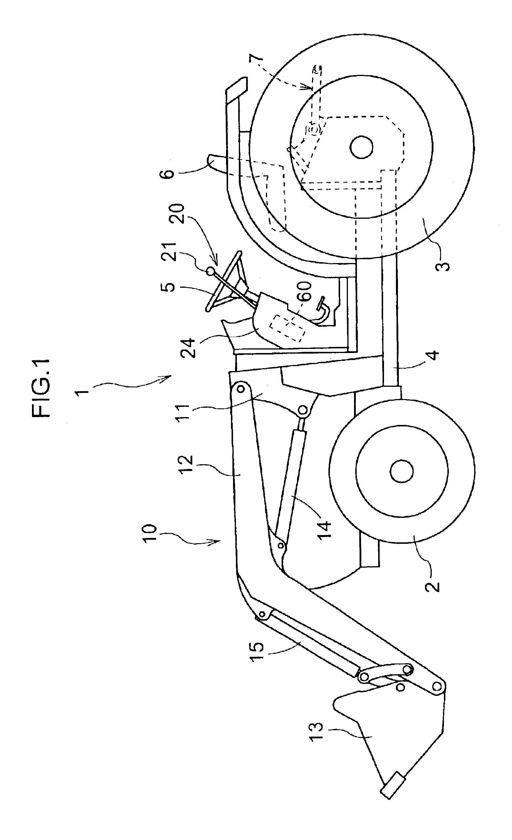
FIG. 1 shows a tractor 1 using a hydraulic control apparatus relating to the present invention and mounting a front loader 10 as a bucket operating implement. The tractor 1 includes front wheels 2, rear wheels 3 and a tractor vehicle body 4 supported on the ground surface by the front and rear wheels 2, 3. And, on the tractor vehicle body 4, there are mounted such components as an engine (not shown), a steering wheel 5, an operator's seat 6, a three-point link mechanism 7 for a cultivating machine, etc.

The front loader 10 includes masts 11 attached respectively to a pair of right and left mounts provided on opposed sides of the tractor vehicle body 4, a boom 12 pivoted to the masts 11 to be vertically pivotable, a bucket 13 pivotally attached to the leading end of the boom 12, a boom cylinder 14 for vertically pivoting the boom 12 and a bucket cylinder 15 for pivoting the bucket 13 between a roll back position and a dump position.

The tractor 1 mounting such front loader 10 described...


PUM


Abstract

A hydraulic control apparatus for controlling a hydraulic cylinder for an implement selectively mounted to a work vehicle. The apparatus includes a hydraulic power source, a four-position changeover control valve disposed between the hydraulic cylinder and the hydraulic power source, and an operational mechanism for operating the four-position changeover control valve. The four-position changeover control valve has a first position for moving a rod of the hydraulic cylinder in one direction, a second position for stopping the rod of the hydraulic cylinder, a third position for moving the hydraulic cylinder rod at a high speed in the other direction with using a function of a regenerative circuit and a fourth position for moving the hydraulic cylinder rod in the other direction at a standard speed without using the function of the regenerative circuit, in the mentioned order. The operational mechanism includes, along an operational movement path thereof, a rollback position, a neutral position, a rapid dump position and a standard dump position, the rollback position corresponding to the first position, the neutral position corresponding to the second position, the rapid dump position corresponding to the third position, the standard dump position corresponding to the fourth position, respectively.

Description

BACKGROUND OF THE INVENTION1. Field of the InventionThe present invention relates to a hydraulic control apparatus for controlling a hydraulic cylinder for an implement selectively mounted on a work vehicle.2. Description of the Related ArtAn example of a work vehicle using the above-noted type of hydraulic control apparatus is a tractor type front loader. For instance, in the case of such front loader known from Japanese Patent Application “Kokai” No.: Hei. 9-316915, a boom to which a bucket is pivotally attached is mounted to a tractor frame. And, a boom cylinder for lifting up / down this boom and a bucket cylinder for pivoting the bucket are controlled by hydraulic control valves provided respectively therefor. In this case, the hydraulic control valve for the bucket cylinder is constructed as a three-position changeover control valve having a rollback position, a neutral position and a dump position. Further, at the dump position, there is formed a so-called “regenerative circuit...

Claims


Application Information

Patent Timeline
IPC IPC(8): E02F9/22F15B11/00F15B11/024G05G9/047G05G9/00G05G5/00F15B13/04F15B13/00E02F3/43
CPCE02F9/2217G05G9/047G05G5/005F15B11/024F15B2013/0413F15B2211/20523F15B2211/30525F15B2211/3116F15B2211/3127F15B2211/3133F15B2211/31576F15B2211/324F15B2211/71F15B2211/78F15B2211/88Y10T137/87072F15B11/00
Inventor KOROGI, ISAO
Owner KUBOTA LTD
Why Eureka
Try Eureka