Machine press

a machine press and press body technology, applied in forging/pressing/hammering apparatus, forging/hammering/pressing machines, shaping tools, etc., can solve the problems of eccentric load in the frame in the lateral direction, disconnecting rod undulates vertically, and displaced vertical thrust load

Inactive Publication Date: 2005-03-29
AIDA ENG LTD
View PDF18 Cites 10 Cited by
  • Summary
  • Abstract
  • Description
  • Claims
  • Application Information

AI Technical Summary

Benefits of technology

Moreover, the above embodiment may further provide a stay that lat

Problems solved by technology

In such cases, one drawback is that the connecting rod undulates vertically.
Furthermore, vertical movement by the connecting rod causes the thrust load to b

Method used


Image

  • Machine press
  • Machine press
  • Machine press

Examples


second embodiment

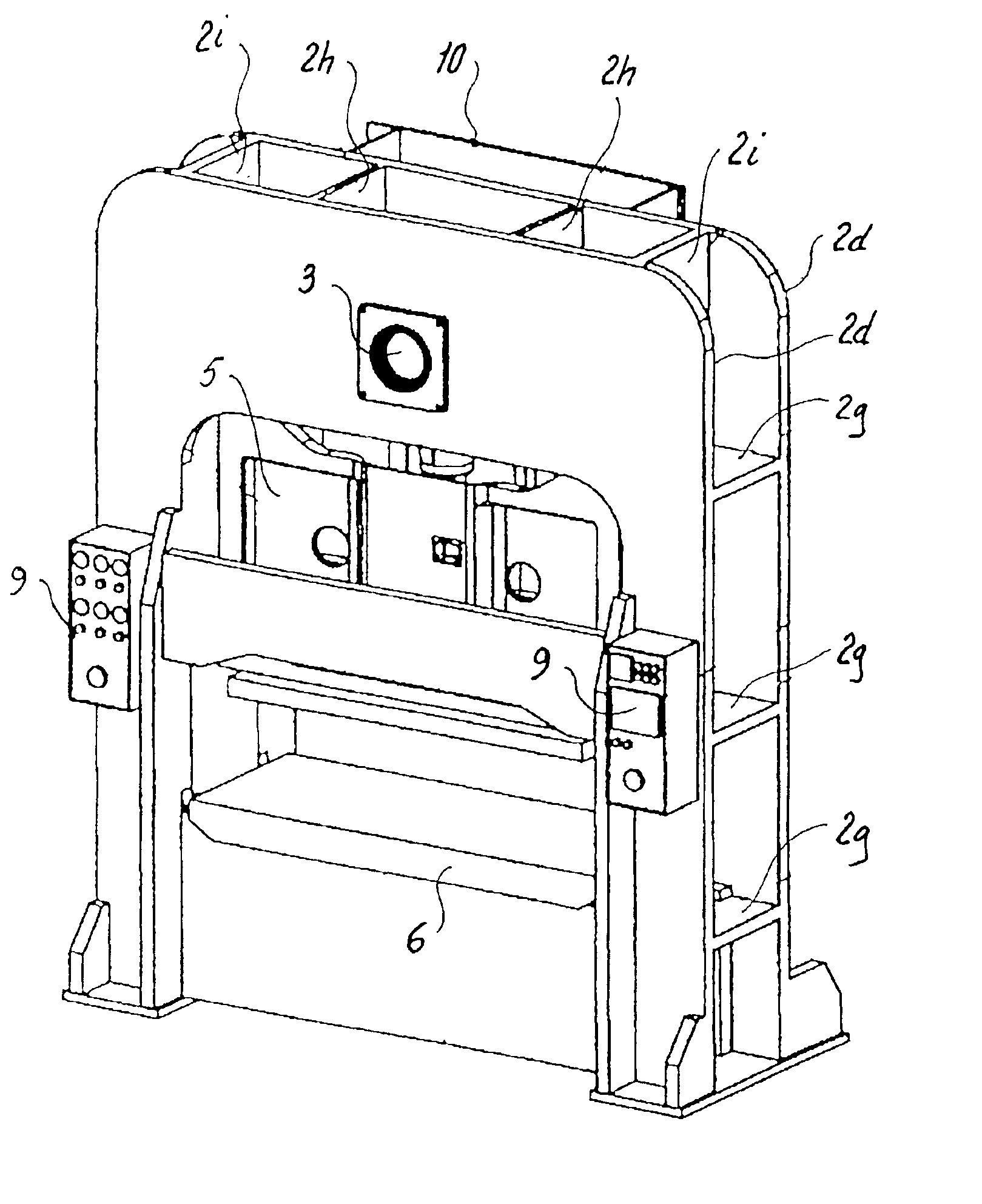
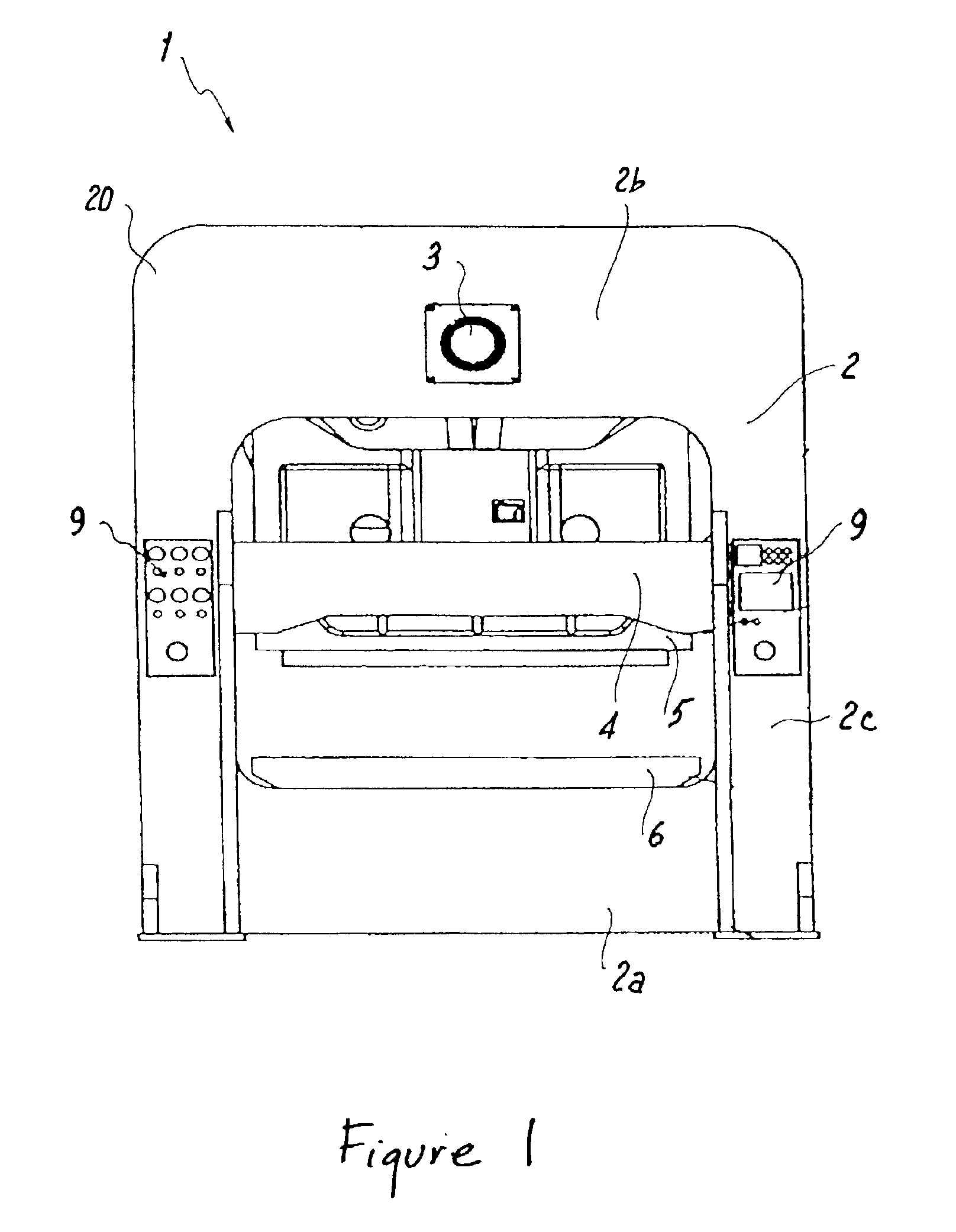
In the preferred embodiment, main plates 2d are ring-shaped, a single plate with a hole in the center thereof. The shape of main plates 2d are designed to naturally bear the press load. In a second embodiment, a single plate is welded to the inside of main plates 2d to further increase the rigidity of bed portion 2a. As illustrated in FIGS. 6 and 7, a bed plate 13 is welded to the inside of main plate 2d and bolster 6 is affixed atop the bed plate 13.

third embodiment

In a third embodiment, ring-shaped main plates 2d are now an inverted U-shaped plate 102d, and a bed 102a is welded to the inside of a front inverted U-shaped plate 102e and a back inverted U-shaped plate 102f.

Referring now to FIGS. 8 and 9, bed 102a is located between inverted U-shaped plates 102d. In the current embodiment, bed 102a is welded to inverted U-shaped plates 102d. The thickness of the plates for bed 102a may be selected without being restricted by the thickness of inverted U-shaped plates 102d. Bolster 6 is secured atop bed 102a and the longitudinal span defined by bolster 6, located inside inverted U-shaped plates 102d, may be made shorter than the span in the first or second embodiments.

Other than the opening in the lower portion, inverted U-shaped plates 102d are the same as ring-shaped main plates 2d. Therefore, inverted U-shaped plates 102d have a crown 102b and columns 102c similar to those of the ring-shaped main plates 2d.

The present device is capable of prov...


PUM


Abstract

A simple structure is provided for the frame by changing the orientation of the crank mechanism so as to orient the crankshaft longitudinally. More specifically, the structure includes two ring-shaped main plates are provided in the front and back and are connected by means of connector plates. An upwardly and downwardly movable slide for the machine press is provided in a space demarcated by four column portions of the ring-shaped main plates and a bolster is provided atop a bed of the ring-shaped main plates. A crankshaft oriented longitudinally is provided at the crown portion of the ring-shaped main plates, and the slide is moved upward and downward by a drive mechanism that includes the crankshaft.

Description

TECHNICAL FIELDThe present invention relates to a machine press. The term “machine press” refers to those press machines wherein a press is driven by a mechanical drive mechanism. This includes presses driven by a crank mechanism, knuckle mechanism, or other link mechanism but excludes oil-pressure presses and other hydraulic presses.BACKGROUNDThe crankshaft of a machine press is oriented horizontally to harness the power to drive an automated device. The horizontal orientation is for reasons of position, rotational direction, and other factors. The crankshaft is integrated with a connecting rod so as to form a crank mechanism. In such cases, one drawback is that the connecting rod undulates vertically. Furthermore, vertical movement by the connecting rod causes the thrust load to be displaced vertically. To compensate for the displacement of the thrust load, the frame of the machine press is required to be much stronger longitudinally, usually by increasing the thickness of the pre...

Claims


Application Information

Patent Timeline
IPC IPC(8): B30B15/04
CPCB30B15/048B30B15/04
Inventor KANAMARU, HISANOBUTAKAO, ITOFUJIMORI, HIROMICHI
Owner AIDA ENG LTD
Why Eureka
Try Eureka