Saddle tank siphon primer

a technology of siphoning primer and saddle tank, which is applied in the direction of liquid fuel feeders, machines/engines, bends, etc., can solve problems such as fuel flow interruption, and achieve the effects of reducing flow rate, reducing pressure, and improving efficiency

Inactive Publication Date: 2005-03-29
TI GRP AUTOMOTIVE SYST LLC
View PDF27 Cites 29 Cited by
  • Summary
  • Abstract
  • Description
  • Claims
  • Application Information

AI Technical Summary

Benefits of technology

Objects, features and advantages of this invention include providing a fuel delivery system that is more efficient when compared with systems currently used in that the pump supplies fuel to the pick-up at a lower flow rate and lower pressure than conventional jet pumps currently used in the industry. The fu

Problems solved by technology

While the fuel delivery systems commonly known in the art are capable of drawing fuel from the different sections within the tank, they often draw the fuel independ

Method used


Image

  • Saddle tank siphon primer
  • Saddle tank siphon primer
  • Saddle tank siphon primer

Examples


Embodiment Construction

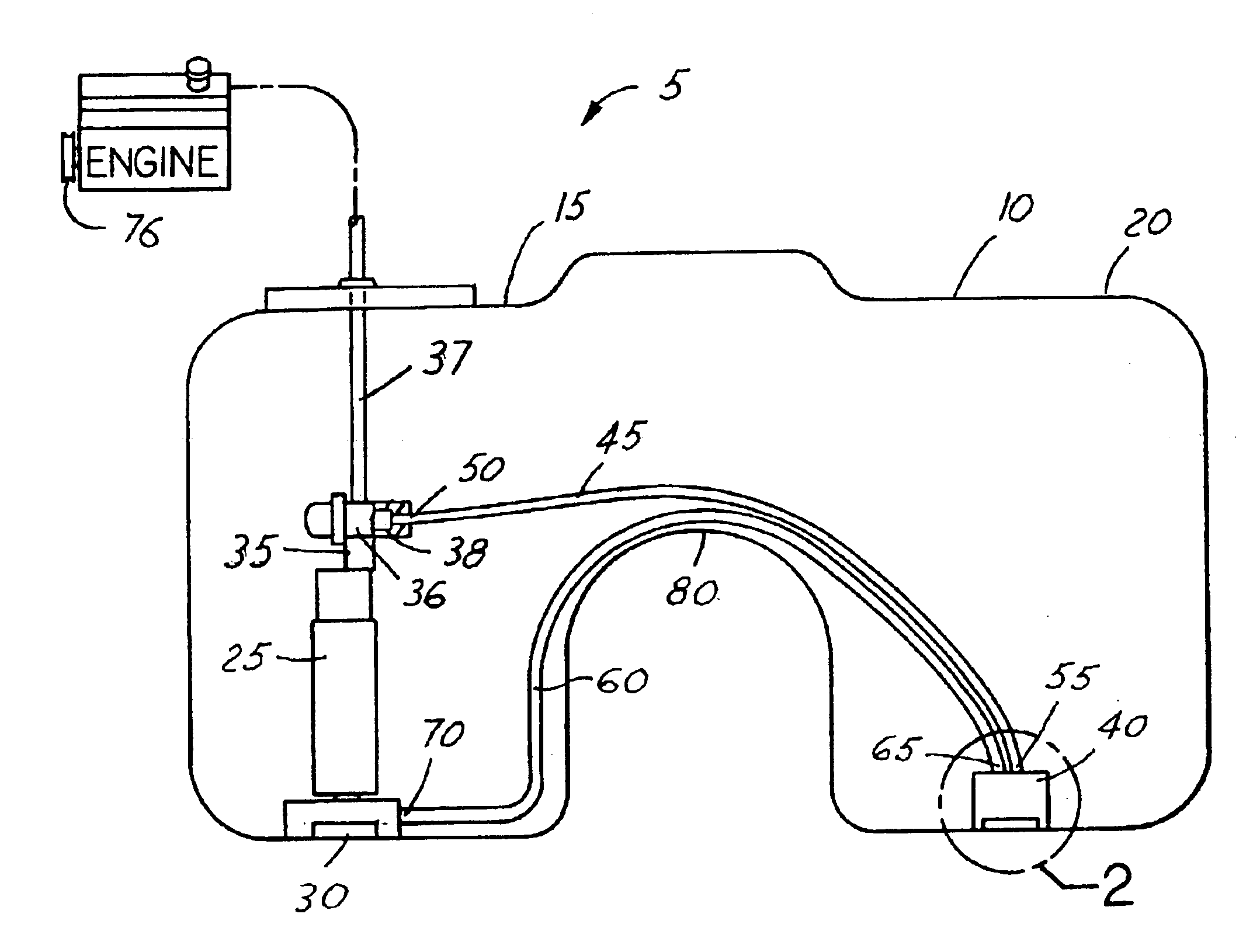
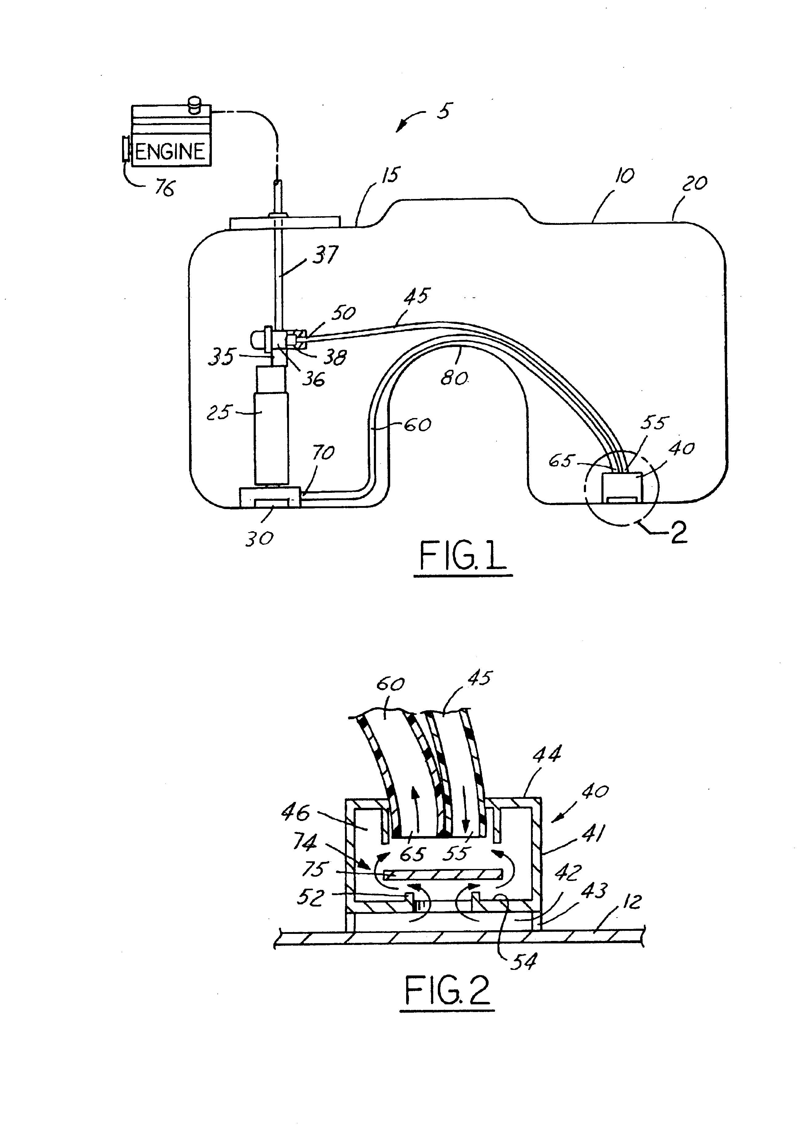
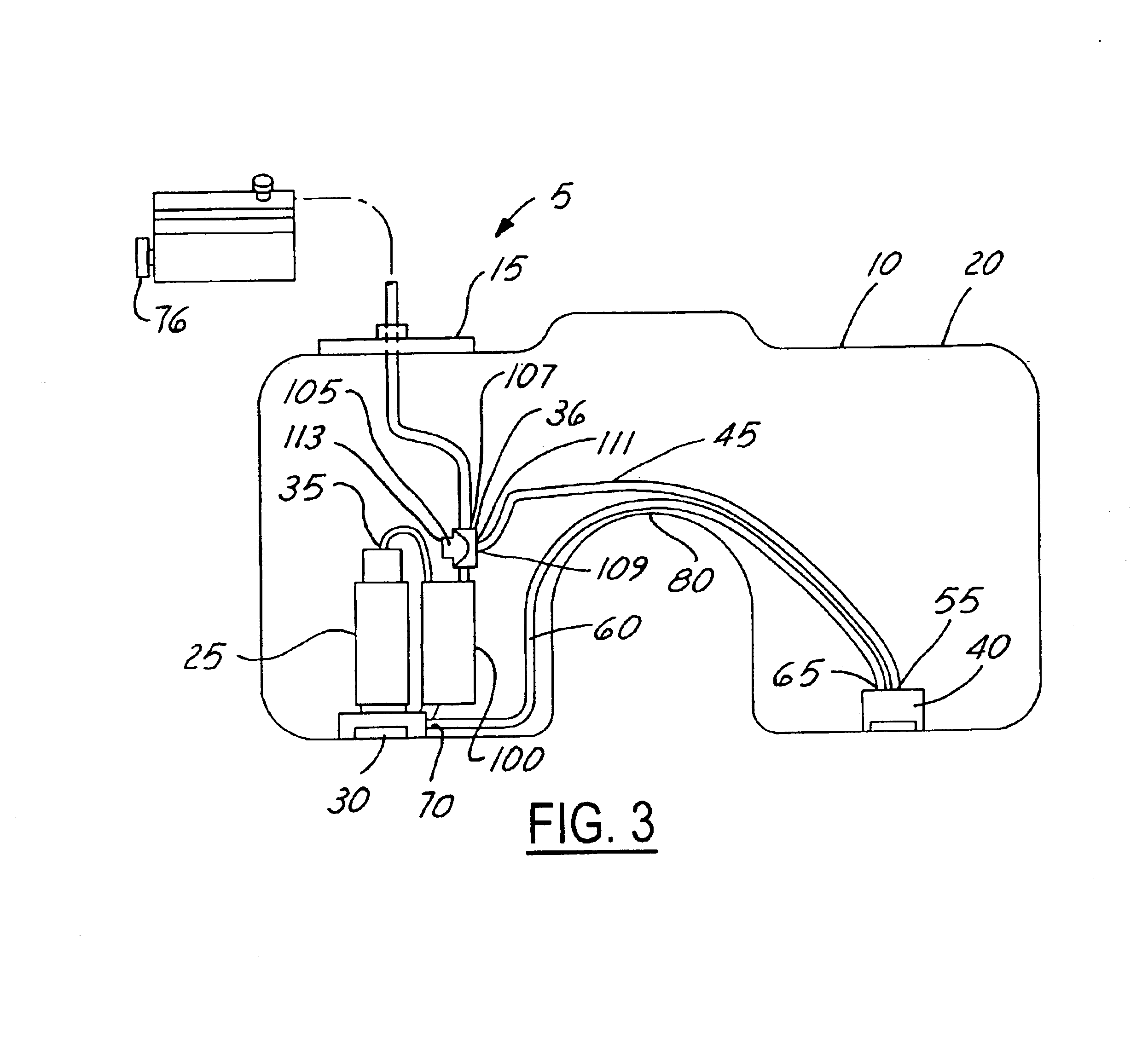
FIG. 1 illustrates a fuel delivery system 5 for a vehicle that includes separate multiple fuel tanks (not shown), or a fuel tank 10 having two sections 15 and 20. The saddle-shaped fuel tank 10 has an electric fuel pump 25 disposed within the first section 15. The fuel pump 25 includes an inlet 30 for drawing liquid fuel from the fuel tank 10 and an outlet 35 for supplying the liquid fuel to an engine 76 and to a pick-up 40 disposed in the second section 20 of the fuel tank 10. Fuel is supplied to the engine 76 through a tee fitting 36 connected to the pump outlet 35 and a line 37 and to the pick-up 40 through a line 45 connected to the tee fitting 36 at one end 50 and to the pick-up 40 at another end 55. A siphon line 60 is connected to the pick-up 40 at one end 65 and at the other end 70 terminates immediately adjacent the bottom of the first section 15. Preferably the end 70 of the siphon line 60 also terminates immediately adjacent the inlet 30 of the pump 25. The flow of liquid...


PUM


Abstract

A fuel delivery system including a fuel tank having multiple sections. A fuel pump is disposed in a first section with an inlet for drawing liquid fuel from the first section and an outlet for supplying the fuel to an engine and to a pick-up disposed in the second section. A siphon line is connected to the pick-up at one end and terminates in the first section at another end. A fuel inlet of the pickup communicates with the siphon line through a valve member that is actuated to open and closed positions. In operation, the fuel pump provides a flow of liquid fuel to the pick-up to purge and prime the siphon line which normally maintains a substantially equal liquid fuel level in the first and second sections of the fuel tank. In some conditions, the valve closes to prevent reverse flow of fuel from the first section to the second section of the tank.

Description

FIELD OF THE INVENTIONThis invention relates generally to fuel delivery systems for internal combustion engines and more particularly to fuel delivery systems with dual fuel tanks or a tank having separate sections.BACKGROUND OF THE INVENTIONThe use of multi-chambered fuel tanks or multiple fuel tanks for vehicles such as trucks, boats or motorcycles is known in the art. For example, the use of a fuel tank having two distinct sections, commonly known as a saddle tank, provides a tank which effectively functions as more than one tank at certain fuel levels. Current fuel delivery systems are designed to draw fuel from each tank, or each distinct section of a tank and deliver the fuel to an engine.While the fuel delivery systems commonly known in the art are capable of drawing fuel from the different sections within the tank, they often draw the fuel independently and unequally from the various sections. The unequal draw of fuel from various sections of the tank leads to different fuel...

Claims


Application Information

Patent Timeline
IPC IPC(8): F02M37/10F02M37/08F04F10/00F02M37/00
CPCF02M37/0023F04F10/00F02M37/0094F02M37/10B60K2015/03118F02M37/0058Y10T137/274Y10T137/2842Y10T137/2877Y10T137/86212
Inventor ATWOOD, JEFFREY M.GILMOUR, DANIEL A.
Owner TI GRP AUTOMOTIVE SYST LLC
Why Eureka
Try Eureka