Steam-cooling-type turbine

Inactive Publication Date: 2005-03-29
MITSUBISHI HITACHIPOWER SYST LTD
View PDF7 Cites 12 Cited by
  • Summary
  • Abstract
  • Description
  • Claims
  • Application Information

AI Technical Summary

Benefits of technology

It is an object of the present invention to provide a steam-cooling-type gas turbine which can maintain

Problems solved by technology

Besides the steam-cooling-type gas turbine of the blade ring integrated structure, the problem

Method used


Image

  • Steam-cooling-type turbine
  • Steam-cooling-type turbine
  • Steam-cooling-type turbine

Examples


second embodiment

The second embodiment makes it possible to achieve virtually the same functions and effects as the aforementioned first embodiment.

In the first and second embodiments, the blade ring 1 has an integral structure. However, the steam-cooling-type gas turbine of the present invention may have a blade ring having a separate structure.

Moreover, in the first and second embodiments, the warming-up steam to the front-stage moving blade 8 and the cooling steam to the tail cylinder 36 are commonly used. However, in the steam-cooling-type gas turbine of the present invention, the warming-up steam to the front-stage moving blade 8 and the cooling steam to the tail cylinder 36 may be provided in a separate manner.

As clearly described above, the steam-cooling-type gas turbine of the present invention is provided with the communication passages the number of which is the same as that of the front-stage stator blades and the rear-stage stator blades are placed so that more communication passages are...


PUM


Abstract

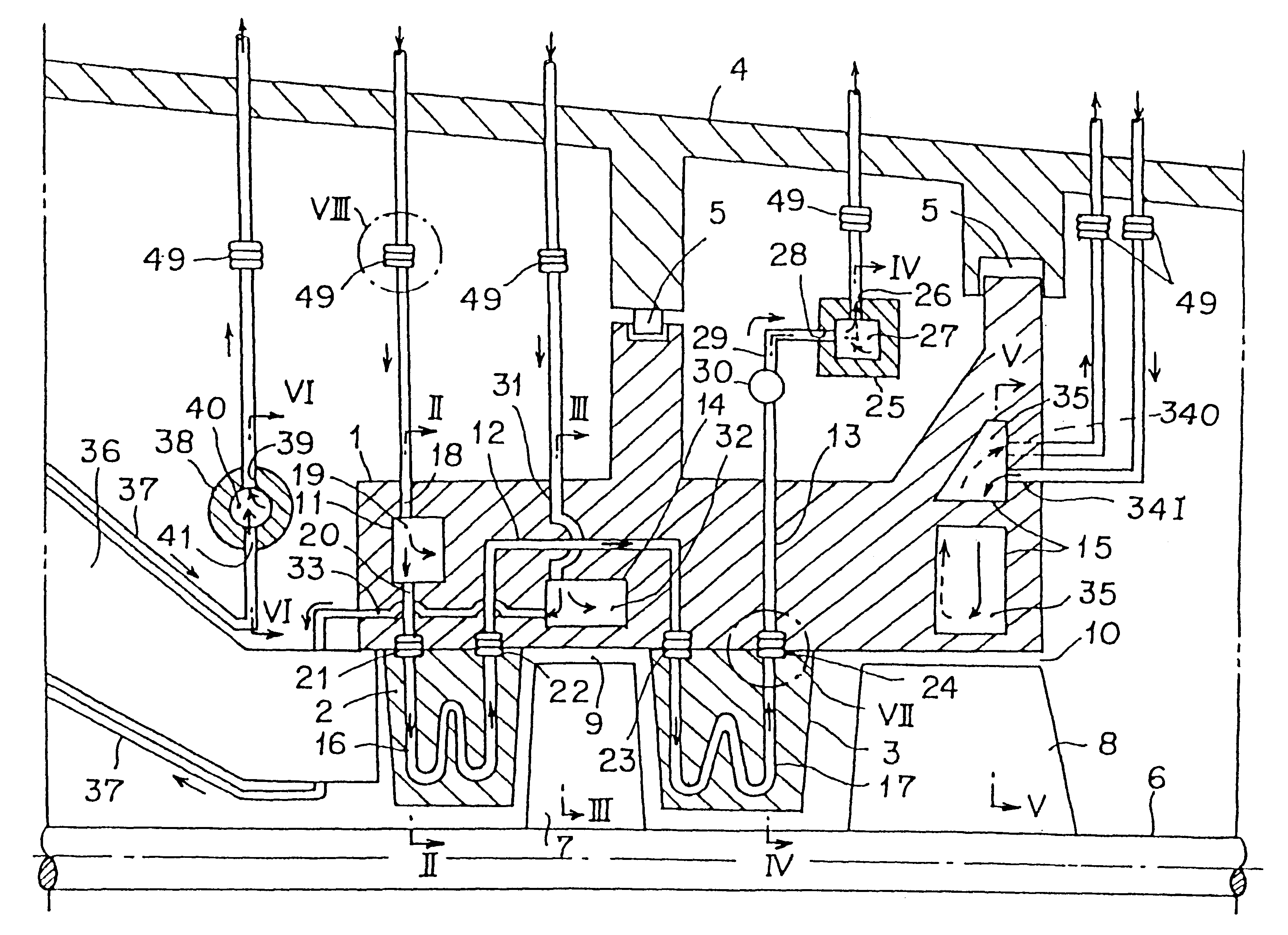
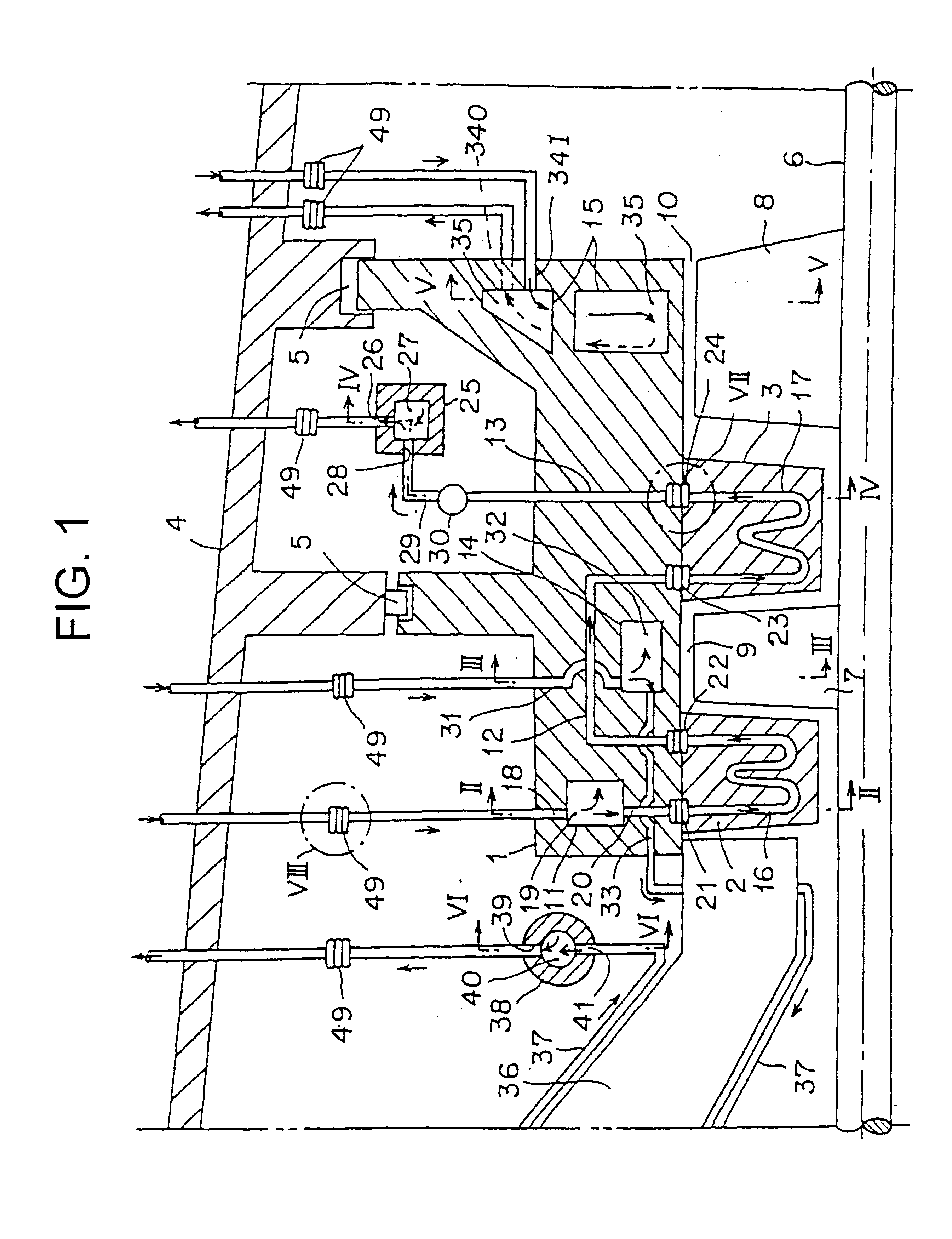
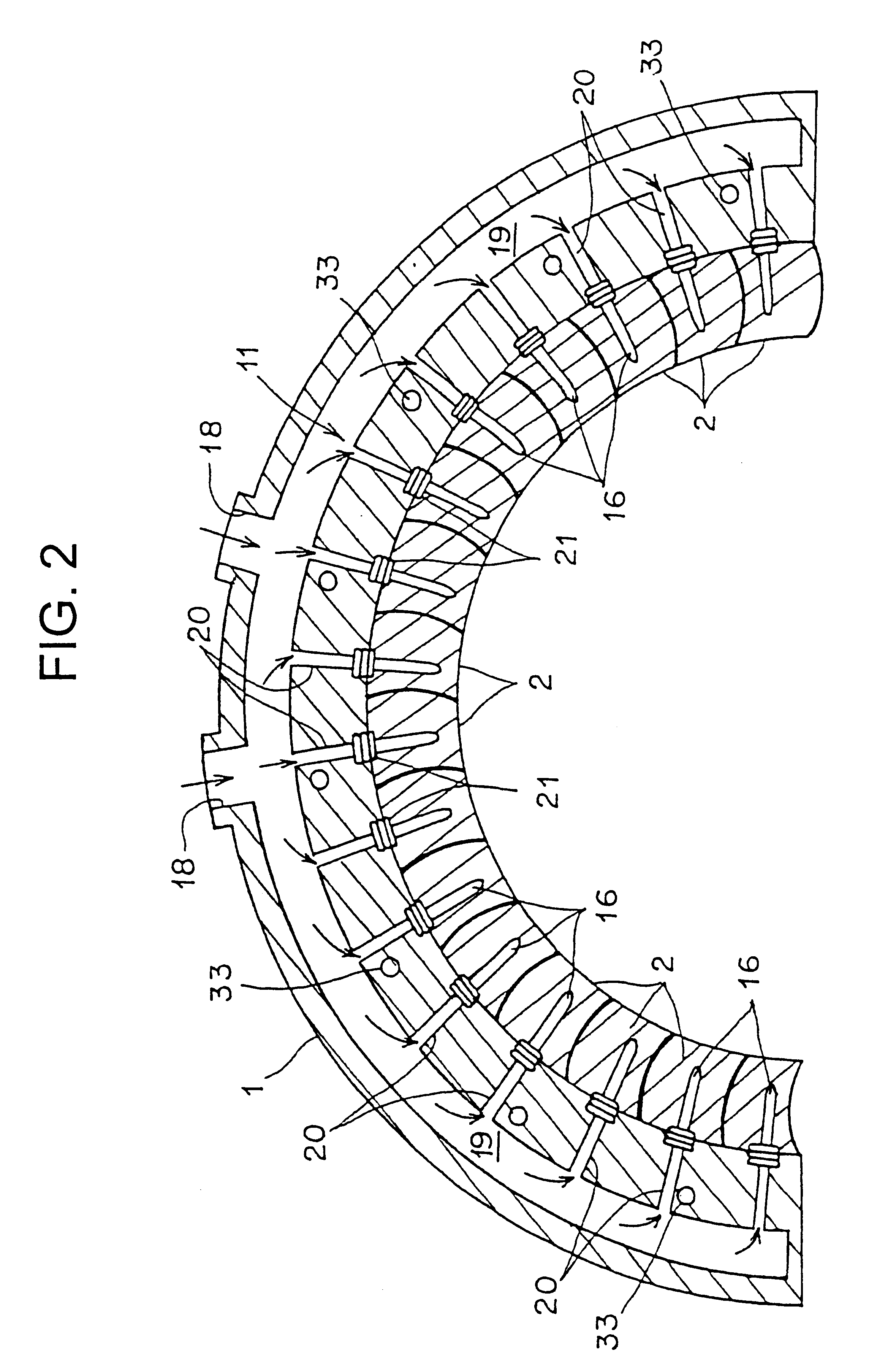
The steam-cooling-type gas turbine is provided with communication passages in number equal to that of the front-stage stator blades and the rear-stage stator blades. Many communication passages are placed in the blade ring densely. As a result, in the blade ring, the temperature difference between the portion having the communication passages and the portion without the communication passages becomes smaller. This makes it possible to minimize the thermal deformation of the blade ring, thereby making it possible to provide uniform clearance between the fixed side such as the blade ring and the rotary side members.

Description

FIELD OF THE INVENTIONThe present invention relates to a steam-cooling-type gas turbine that cools stator blades by cooling stream. More particularly, this invention relates to a steam-cooling-type gas turbine that can maintain a clearance evenly between a blade ring, etc., on the fixed side and a moving blade on the rotator side.BACKGROUND OF THE INVENTIONA conventional steam-cooling-type gas turbine has been disclosed in, for example, Japanese Patent Application Laid-Open No. 11-182205 filed by the applicant of the present invention. The steam-cooling-type gas turbine described in this reference will be explained with reference FIG. 12 and FIG. 13.In FIG. 12, reference numeral 100 indicates a blade ring. The blade ring 100 is provided with one-half ring-shape members that are longitudinally combined so as to be detachably attached to each other, thereby forming a ring shape. In the blade ring 100, plurality of (for example, 32) front-stage stator blades (for example, first-stage s...

Claims


Application Information

Patent Timeline
IPC IPC(8): F01D11/24F01D25/12F01D25/08F01D11/08F02C7/16F01D9/02F01D9/04F01D25/00F01D25/24F02C7/28
CPCF01D11/24F01D25/12F02C7/16F05D2260/205F05D2260/2322
Inventor TANIOKA, TADATERU
Owner MITSUBISHI HITACHIPOWER SYST LTD
Why Eureka
Try Eureka