

Propulsion unit network
a technology of propulsion unit and network, which is applied in the direction of marine propulsion, special-purpose vessels, vessel construction, etc., can solve the problems of creating certain difficulties in the construction of watercraft with multiple propulsion units, and achieve the effect of simplifying the assembly of watercra
- Summary
- Abstract
- Description
- Claims
- Application Information
AI Technical Summary
Benefits of technology
Problems solved by technology
Method used
Image

Examples
Embodiment Construction
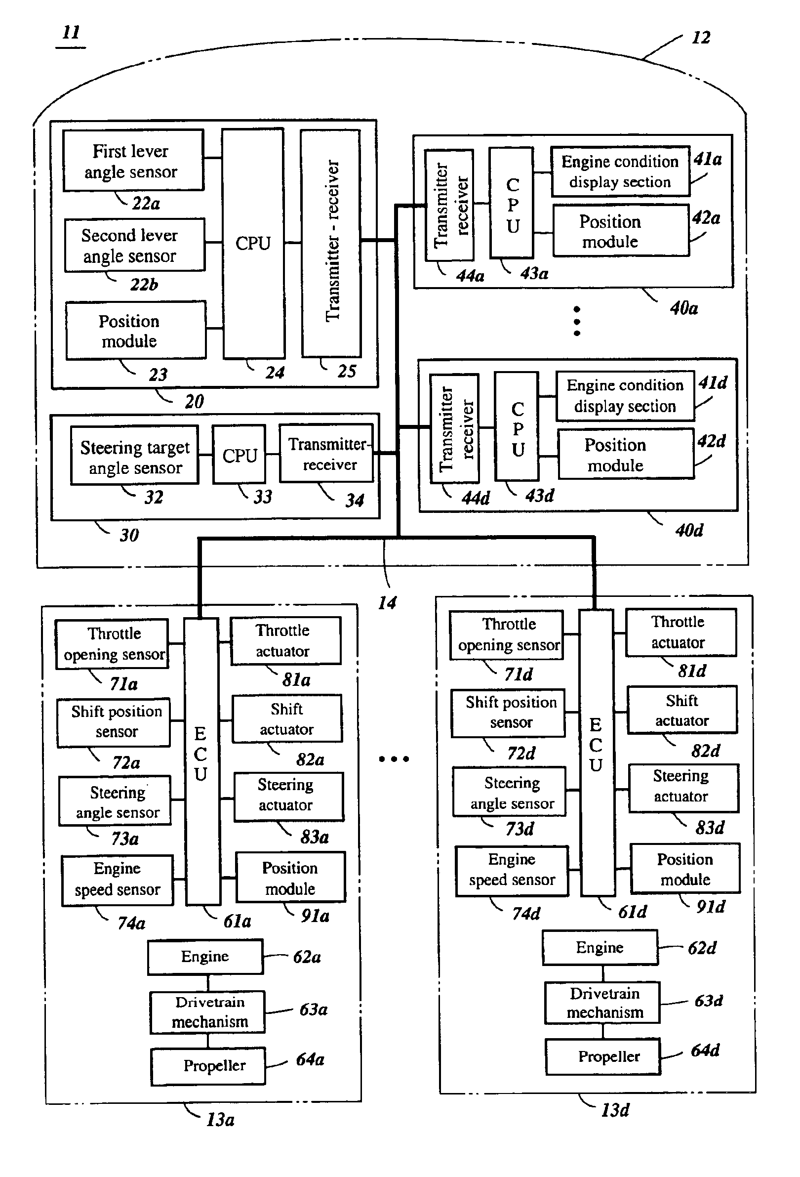
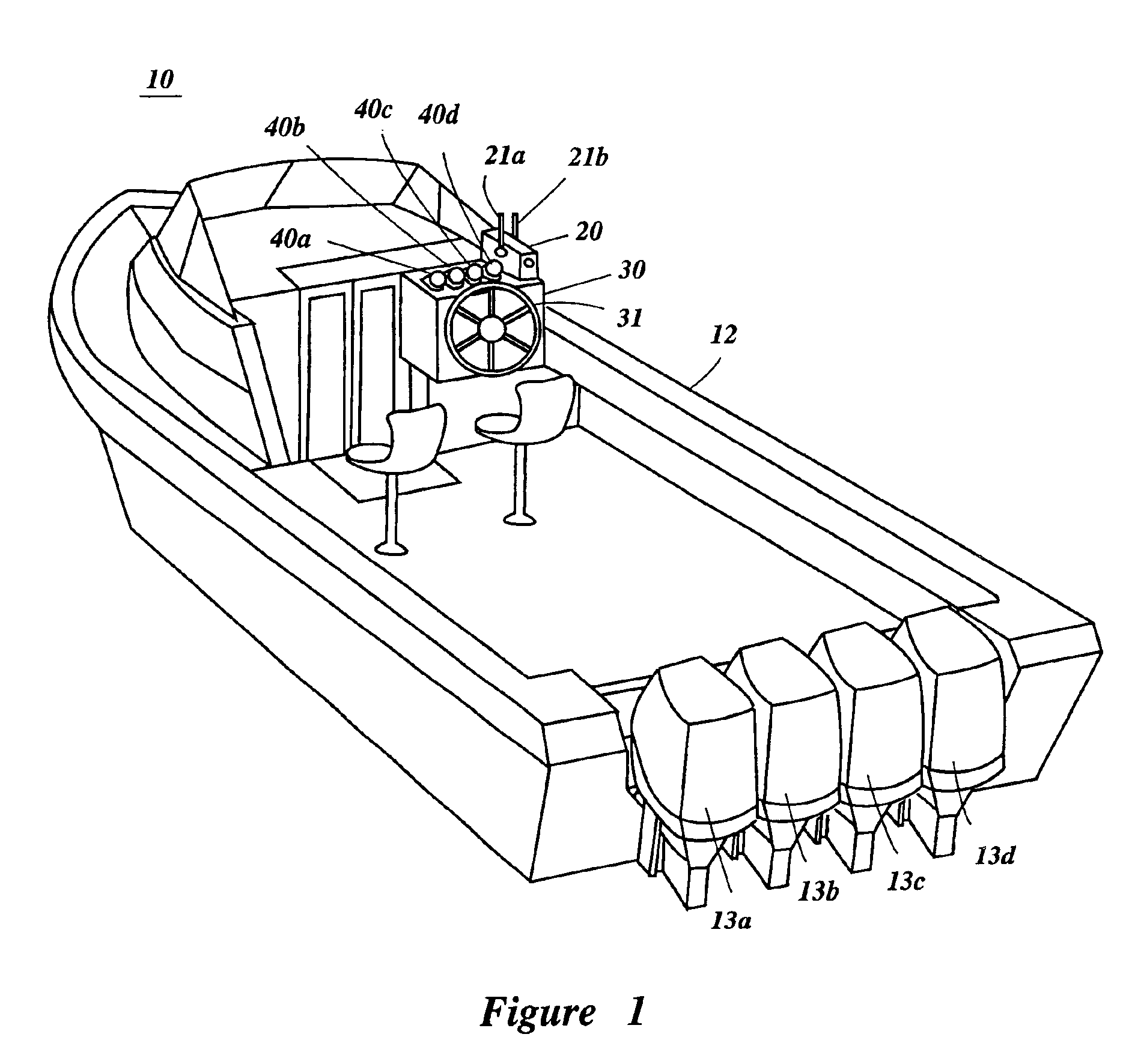
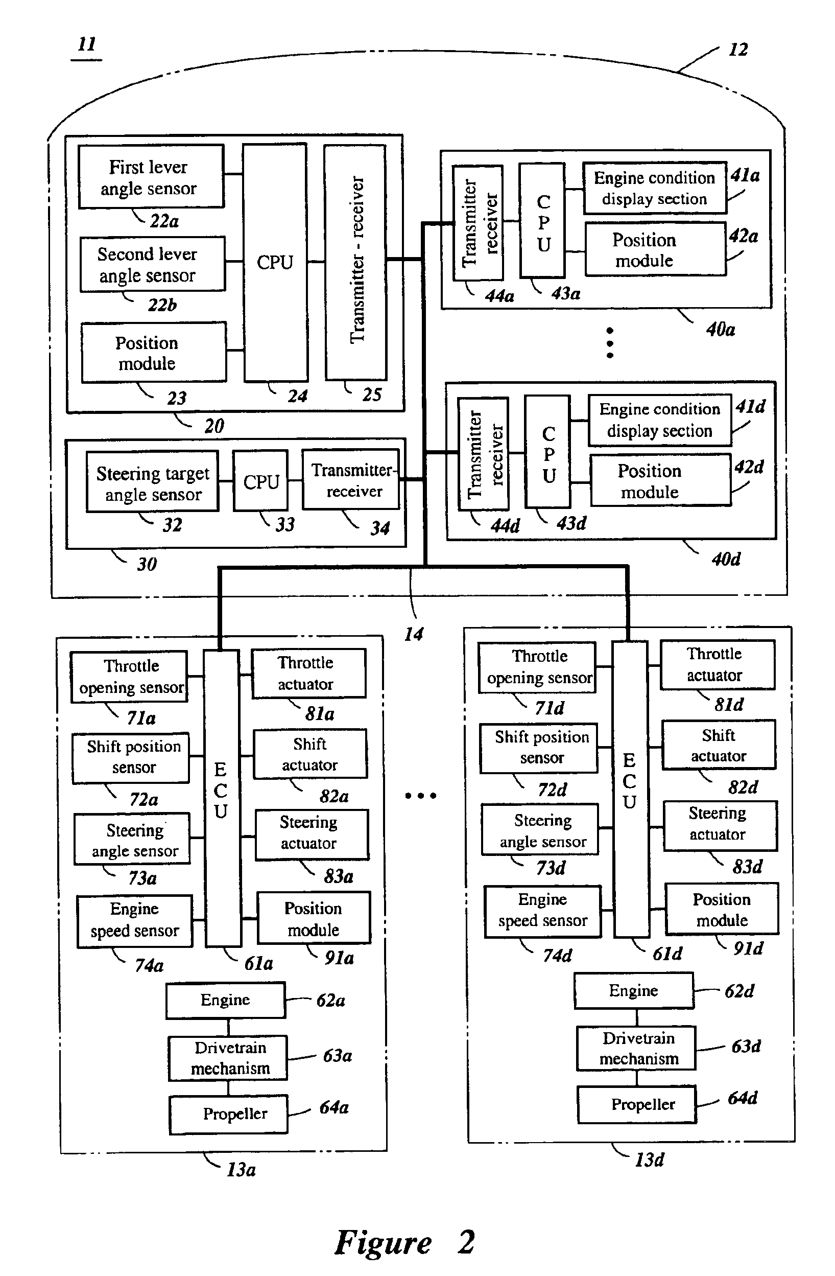
With initial reference to FIG. 1, a watercraft 10 advantageously includes a network connecting at least one outboard motor with at least one other components in the watercraft 10 and configured in accordance with certain features, aspects, and advantages of the present invention. The watercraft 10 provides an exemplary environment in which the network has particular utility. The network of the present invention may also find utility in applications where multiple engines are used in parallel.
As shown in FIG. 1, the watercraft 10 is comprised of a hull 12 and four outboard motors 13a-13d. The hull 12 is provided with a remote control 20 connected with remote control levers 21a and 21b, a steering unit 30 connected with a steering wheel 31, and engine condition display devices 40a-40d corresponding respectively to the outboard motors 13a-13d.
As the outboard motors 13a-13d are operated with the remote control levers 21a, 21b and the steering wheel 31, conditions of each of the outboar...
PUM
 Abstract
Description
Claims
Application Information