Method of cutting material for use in implantable medical device

a medical device and implantable technology, applied in the field of implantable medical devices, can solve the problems of affecting the durability of the device, putting a patient at substantial risk, and causing dislocation of the patient,

Inactive Publication Date: 2005-03-29
3F THERAPEUTICS
View PDF34 Cites 407 Cited by
  • Summary
  • Abstract
  • Description
  • Claims
  • Application Information

AI Technical Summary

Benefits of technology

Accordingly, there is a need for a method and apparatus for cutting segments of material for use in implantable medical devices wherein the segments are cut with precision and consistency, and wherein the cut edges of the segments resist wear when implanted into the body.
In accordance with one embodiment, a method of creating an implantable medical prosthesis is provided. A sheet of pericardium having at least two tissue layers is provided and a segment of tissue is cut out of the sheet of pericardium with a laser beam. The cutting comprises operating a laser at a power and pulse rate such that the beam welds the layers of the pericardium together along a laser cut edge without significantly burning the pericardium adjacent the cut edge.

Problems solved by technology

It is important for such prosthetic devices to be substantially durable, as failure of the device may have drastic consequences for the patient.
As can be appreciated, a prosthetic device that wears out prematurely may put a patient at substantial risk, both because of the possibility of early, sudden failure of the device and because of additional surgery that may be required to replace the device.
The manner in which the segments of material are formed can significantly affect the durability of the device.
For example, if the segments are formed by being cut out of a larger portion of material, the edges of the cut segments may be especially susceptible to premature wear.
Also, imprecise cutting or inconsistencies between cut segments may negatively affect both the operability and durability of the assembled prosthetic device.

Method used


Image

  • Method of cutting material for use in implantable medical device
  • Method of cutting material for use in implantable medical device
  • Method of cutting material for use in implantable medical device

Examples


Embodiment Construction

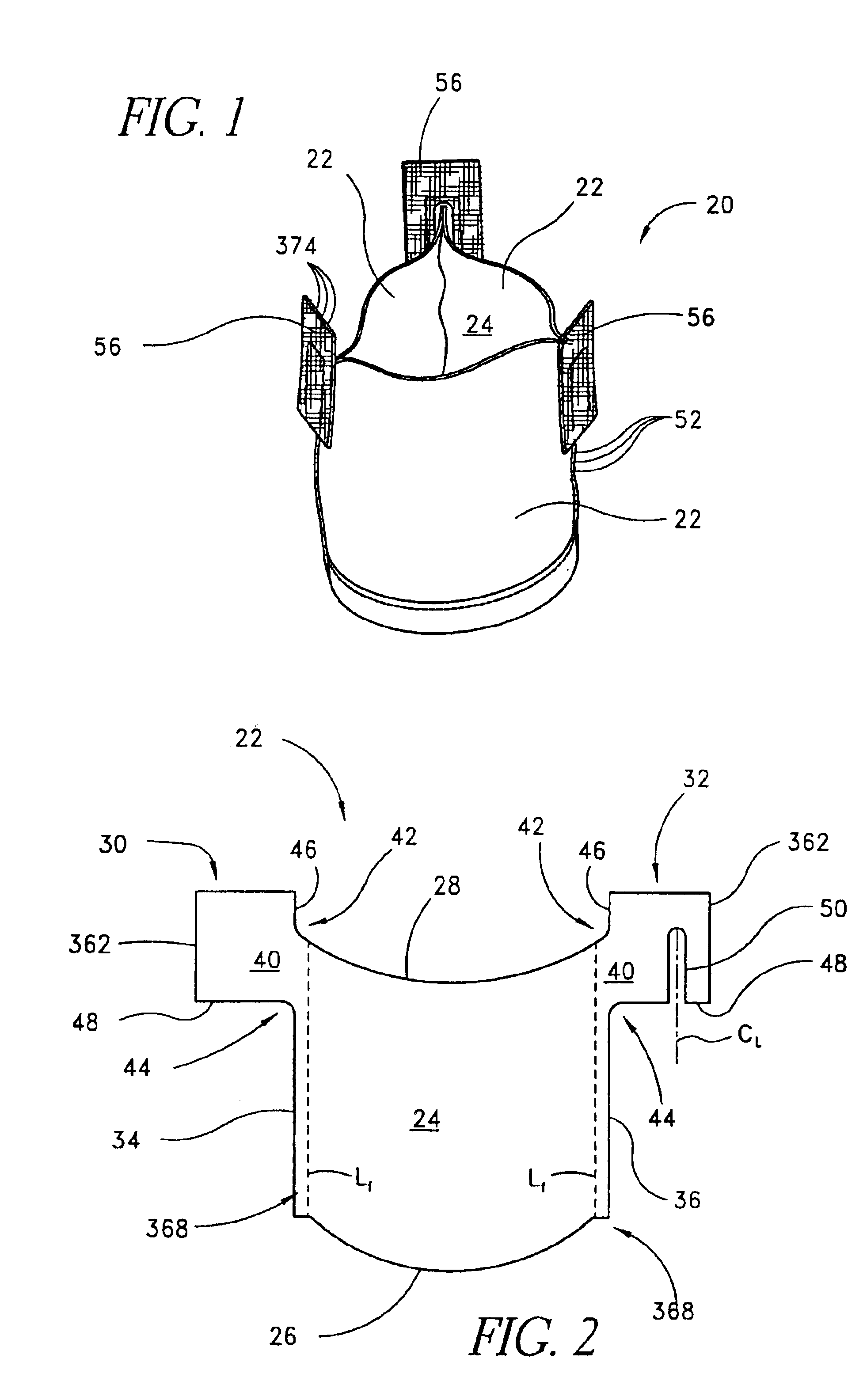
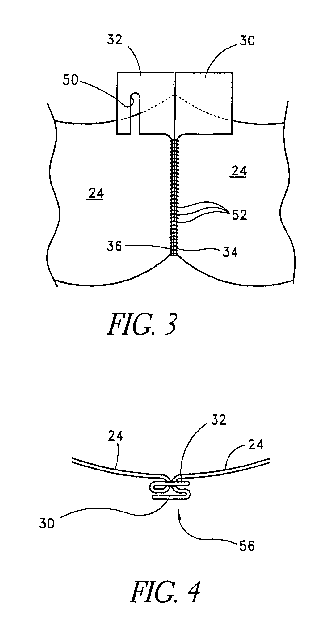
The present invention can be used to cut out segments used when constructing several types of prostheses. One type of prosthesis that particularly benefits from use of the present invention is a replacement heart valve having one or more leaflets that are cut from a source material and assembled to form the valve. FIGS. 1-4 present a prosthetic aortic heart valve 20 constructed in accordance with an embodiment of the present invention. This heart valve 20 is discussed in order to help illustrate aspects and advantages of the invention and is discussed in more detail in the above-referenced application entitled PROSTHETIC HEART VALVE. It is to be understood that other types of implantable prostheses may also benefit from the aspects discussed below.

The aortic heart valve 20 of FIGS. 1-4 comprises three leaflets 22 that are cut out of a generally flat, flexible source material. Each of the three leaflets 22 is cut out according to the pattern shown in FIG. 2. As shown, each leaflet 22...


PUM

PropertyMeasurementUnit
cutting speedaaaaaaaaaa
wavelengthaaaaaaaaaa
diameteraaaaaaaaaa

Abstract

A method of cutting material for use in an implantable medical device employs a plotted laser cutting system. The laser cutting system is computer controlled and includes a laser combined with a motion system. The laser precisely cuts segments out of source material according to a predetermined pattern as designated by the computer. The segments are used in constructing implantable medical devices. The cutting energy of the laser is selected so that the cut edges of the segments are melted to discourage delamination or fraying, but communication of thermal energy into the segment beyond the edge is minimized to avoid damaging the segment adjacent the edge.

Description

BACKGROUND OF THE INVENTION1. Field of the InventionThis invention relates to implantable medical devices, and more particularly relates to forming segments used to construct such implantable medical devices.2. Description of the Related ArtMedical devices are often surgically implanted into a patient in order to assist or replace diseased tissue. For instance, a prosthetic device such as an artificial heart valve can be implanted to replace a defective natural heart valve.It is important for such prosthetic devices to be substantially durable, as failure of the device may have drastic consequences for the patient. As can be appreciated, a prosthetic device that wears out prematurely may put a patient at substantial risk, both because of the possibility of early, sudden failure of the device and because of additional surgery that may be required to replace the device.Some implantable medical devices comprise two or more members or segments of material that are assembled to form the ...

Claims


Application Information

Patent Timeline
Patent Type & Authority Patents(United States)
IPC IPC(8): A61F2/24B23K26/40B23K26/32B23K26/00
CPCA61F2/2415B23K26/3246B23K26/3253B23K26/328B23K26/4055B23K26/4065B23K26/4085B23K26/403Y10T156/1054A61F2220/0075B23K26/32B23K26/324B23K26/40B23K2103/16B23K2103/30B23K2103/38B23K2103/42B23K2103/50
Inventor CALI, DOUGLAS S.MYERS, KEITH E.
Owner 3F THERAPEUTICS
Why Eureka
Try Eureka