Gas discharge tube having multiple stem pins

a technology of gas discharge tube and stem pin, which is applied in the direction of gas-filled discharge tube, discharge tube/lamp details, incadescent body mounting/support, etc., can solve the problems of difficult to generate discharge when the lamp is activated, limited diameter of small holes, and limited number of metallic partition walls, etc., to achieve a small opening area.

Inactive Publication Date: 2005-03-29
HAMAMATSU PHOTONICS KK
View PDF12 Cites 5 Cited by
  • Summary
  • Abstract
  • Description
  • Claims
  • Application Information

AI Technical Summary

Benefits of technology

The present invention has been designed in order to solve the aforementioned problems, and it is a particular object thereof to provide a gas discharge tube in which favorable startability is provided while realizing high luminance, and in which a light-emitting portion assembly fixed inside a hermetically sealed container in a floating state can be securely supported.
Further, the first opening of the first discharge path limiting portion preferably comprises a funnel-shaped part which decreases in diameter from the light exit window toward the anode portion. By means of this funnel-shaped part, discharge can be easily converged in the first opening, whereby an arc ball can be reliably generated in this part and expansion of the arc ball can be appropriately prevented. It is also preferable that a higher voltage be applied to the second discharge path limiting portion than to the first discharge path limiting portion. By employing such a constitution, an appropriate discharge starting voltage can be applied between the first discharge path limiting portion and second discharge path limiting portion in accordance with the potential difference between the cathode portion and anode portion, and thus a starting discharge can be generated smoothly.

Problems solved by technology

However, the following problems exist in the conventional gas discharge tube described above.
Accordingly, as is described in the publication itself, although luminance may indeed be increased by narrowing the discharge path, the discharge starting voltage must be significantly increased as the small holes are reduced in diameter, causing severe limitations on the diameter of the small holes and the number of metallic partition walls.
When high luminance light is to be produced, it is not simply a case of reducing the diameter of the opening parts for narrowing the discharge path since the more the diameter thereof is reduced, the more difficult it becomes to generate discharge when the lamp is activated.

Method used


Image

  • Gas discharge tube having multiple stem pins
  • Gas discharge tube having multiple stem pins
  • Gas discharge tube having multiple stem pins

Examples


first embodiment

(First Embodiment)

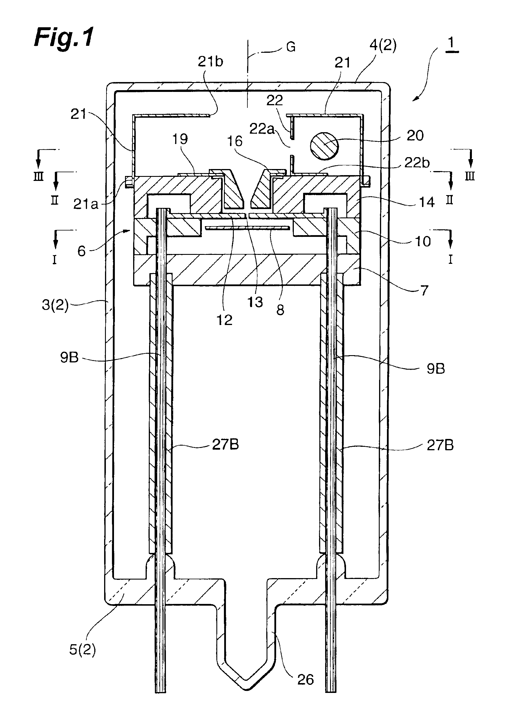
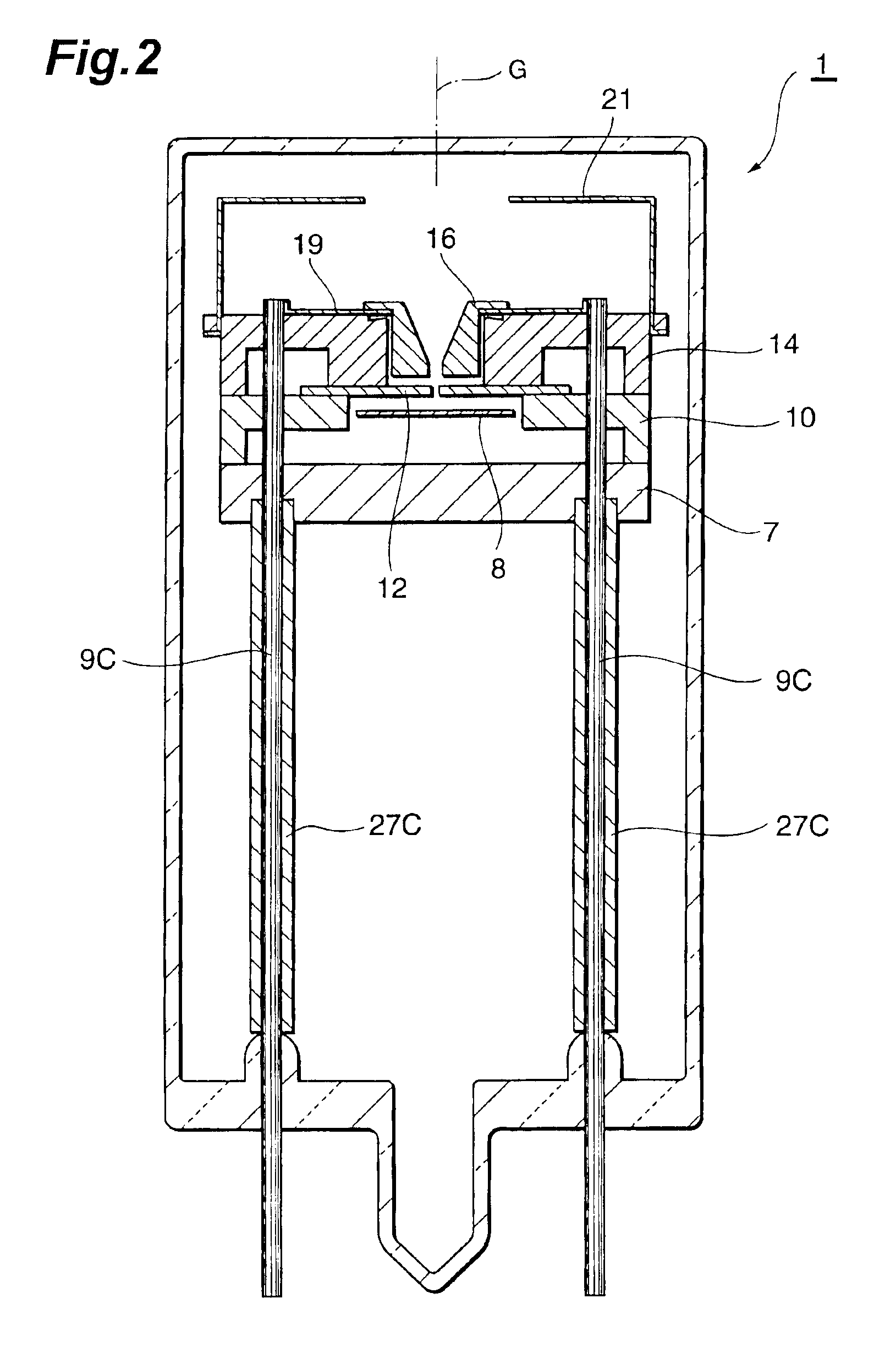
As shown in FIGS. 1 and 2, a gas discharge tube 1 is a head-on type deuterium lamp. The gas discharge tube 1 comprises a glass hermetically sealed container 2 into which deuterium gas is sealed at approximately several hundred Pa. The hermetically sealed container 2 is constituted by a cylindrical side tube 3, a light exit window 4 which seals one side of the side tube 3, and a stem 5 which seals the other side of the side tube 3. A light-emitting portion assembly 6 is housed inside the hermetically sealed container 2.

The light-emitting portion assembly 6 comprises a disk-form electrical insulation portion (first support portion) 7 made of an electrically insulating ceramic. As shown in FIGS. 3 and 4, an anode plate (anode portion) 8 is disposed on the electrical insulation portion 7. A circular main body portion 8a of the anode plate 8 is removed from the electrical insulation portion 7, and two lead portions 8b extending from the main body portion 8a are electric...

second embodiment

(Second Embodiment)

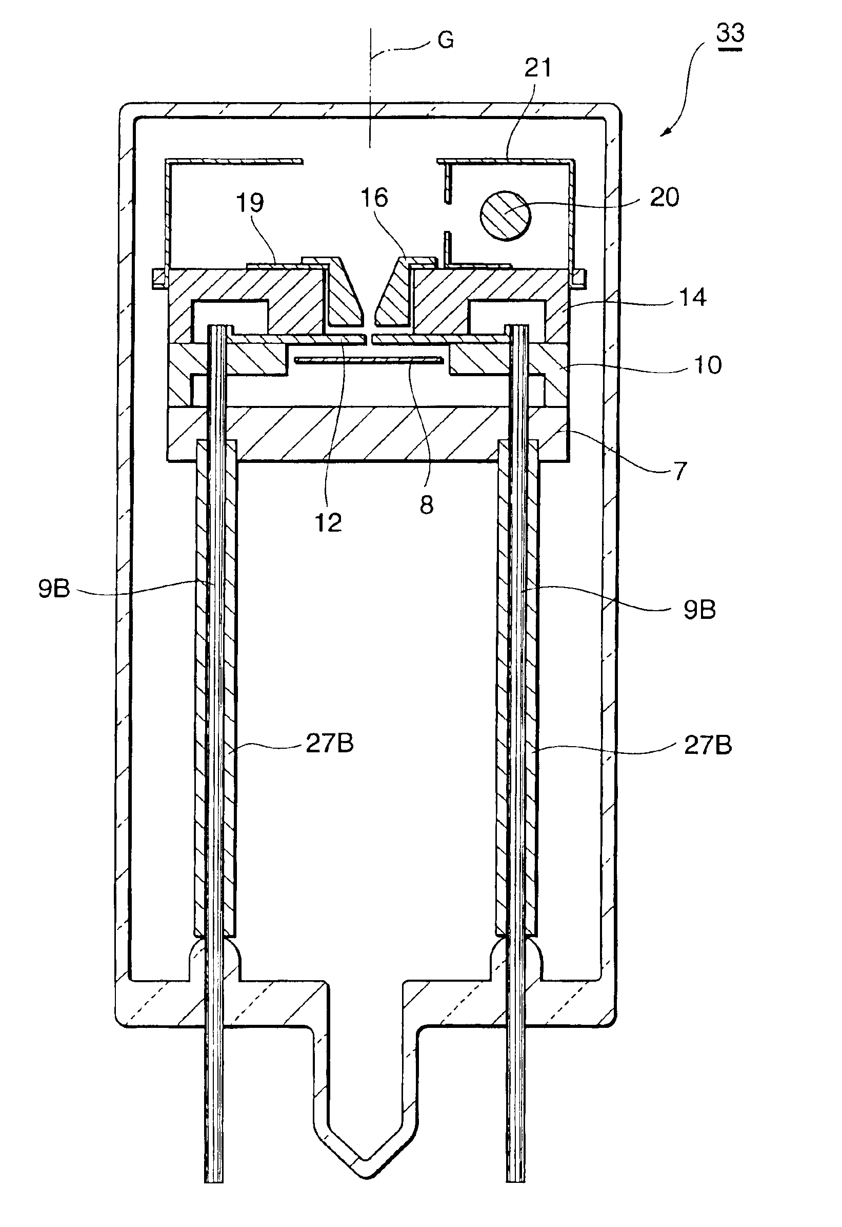
As shown in FIGS. 11 and 12, in a gas discharge tube 33 a second discharge path limiting plate 12 is not fixed by being gripped between a second support portion 10 and a third support portion 14, but instead the second discharge path limiting plate 12 is merely welded to the distal end of stem pins 9B and placed on the second support portion 10. Hence heat discharge from a first discharge path limiting portion 16 and the second discharge path limiting plate 12 can be increased and the amount of sputtering material and evaporated material generated by the first discharge path limiting portion 16 and second discharge path limiting plate 12 can be reduced. As a result the lamp characteristic can be maintained in a stable state over a long time period.

third embodiment

(Third Embodiment)

As shown in FIGS. 13 and 14, in a gas discharge tube 35 a second discharge path limiting plate 12A is disposed in contact with the rear face of an electrical insulation portion (third support portion) 14, and the second discharge path limiting plate 12A is fixed to the electrical insulation portion 14 by metallic rivets 36. Thus the electrical insulation portion 14 and second discharge path limiting plate 12A are integrated. During an assembly operation the rivets 36 are electrically connected to the distal ends of stem pins 9B. By means of such a constitution the ceramic second support portion 10 can be omitted, thereby reducing the number of support portions from three to two. Moreover, heat discharge from the second discharge path limiting plate 12A and anode portion 8 can be increased, and thus the amount of sputtering material and evaporated material generated by the second discharge path limiting plate 12A and anode portion 8 can be reduced. As a result the l...


PUM


Abstract

In order to obtain light of a high luminance in a gas discharge tube of the present invention, a discharge path is narrowed by a first opening 18 and a second opening 13 in collaboration. Further, in order to provide favorable startability in a lamp even when the discharge path is narrowed, a predetermined voltage is applied from the outside to first and second discharge path limiting portions 16, 12. As a result, an active starting discharge which is capable of passing through the first and second openings is produced between a cathode portion 20 and the first and second discharge path limiting portions 16, 12, and thus discharge between the cathode portion 20 and an anode portion 8 is started speedily. Further, the anode portion, cathode portion, first discharge path limiting portion, and second discharge path limiting portion are housed within a light-emitting portion assembly 6 and electrically connected by first through fourth stem pins 9A to 9D, and the stem pins are utilized effectively to support the light-emitting portion assembly.

Description

TECHNICAL FIELDThe present invention relates particularly to a gas discharge tube for use as a light source in a spectroscope, in chromatography, and so on.BACKGROUND ARTJapanese Patent Application Laid-open Publication H6-310101 discloses conventional technology in this field. In a gas (deuterium) discharge tube described in this publication, two metallic partition walls are disposed on a discharge path between an anode and a cathode, a small hole is formed in each partition wall, and the discharge path is narrowed by these small holes. As a result, light of a high luminance can be obtained by means of the small holes on the discharge path. If three or more metallic partition walls are provided, even higher luminance is obtained, and the luminance of the light increases as the small holes are made smaller.DISCLOSURE OF THE INVENTIONHowever, the following problems exist in the conventional gas discharge tube described above. That is, no voltage is applied to the metallic partition w...

Claims


Application Information

Patent Timeline
Patent Type & Authority Patents(United States)
IPC IPC(8): H01J61/00H01J61/68H01J61/36H01J61/54
CPCH01J61/68H01J61/54
Inventor KAWAI, KOJIITO, YOSHINOBU
Owner HAMAMATSU PHOTONICS KK
Why Eureka
Try Eureka