Digital signal conversion apparatus, digital signal conversion method, and computer-readable recording medium in which digital signal conversion program is recorded

a digital signal and conversion method technology, applied in pulse conversion, pulse technique, instruments, etc., can solve the problems of difficult to practically perform 3-value pwm of a digital signal using together with the interpolation method, and the non-linear distortion becomes higher than the case, so as to reduce the quantization noise, reduce the non-linear distortion, and reduce the effect of non-linear distortion

Inactive Publication Date: 2005-03-29
PIONEER CORP
View PDF7 Cites 27 Cited by
  • Summary
  • Abstract
  • Description
  • Claims
  • Application Information

AI Technical Summary

Benefits of technology

The digital signal conversion program recorded on the recording medium of this invention over samples the input digital signal and performs PWM conversion of the over sampled digital signal and a signal having inverted polarity with respect to that digital signal. Furthermore, the digital signal conversion program converts the inputted digital signal to an analog signal by performing the PWM conversion. When the PWM conversion is performed, interpolation is performed by a specified interpolation method for both of the over sampled digital signal and the over sampled digital signal with inverted polarity in order to reduce non-linear distortion. In order to reduce the quantization noise in the audible range of both of these interpolated signals, noise shaping is performed by respective noise-shaping process. The PWM conversion is performed for the noise-shaped signals by PWM conversion process, and the load is driven based on the PWM signals from the two PWM conversion circuits. Therefore, it is possible to reproduce the signal with small non-linear distortion.

Problems solved by technology

However, if 3-value PWM is performed on the interpolated digital signal by merely generating the second PWM signal for the two's complement of the interpolated digital signal, non-linear distortion becomes higher than the case of 2-value PWM, because the second PWM signal for the two's complement of the interpolated digital signal does not approximate a PWM signal for a polarity inverted analog signal.
So, it is difficult to practically perform 3-value PWM of a digital signal using together with the interpolation method.

Method used


Image

  • Digital signal conversion apparatus, digital signal conversion method, and computer-readable recording medium in which digital signal conversion program is recorded
  • Digital signal conversion apparatus, digital signal conversion method, and computer-readable recording medium in which digital signal conversion program is recorded
  • Digital signal conversion apparatus, digital signal conversion method, and computer-readable recording medium in which digital signal conversion program is recorded

Examples


first embodiment

(First Embodiment)

A first embodiment of the digital signal conversion apparatus of this invention will be explained by using FIG. 1 to FIG. 9.

This embodiment is a digital signal conversion apparatus that drives a load using a three-value PWM signal, and together with increasing the accuracy of interpolation and reducing non-linear distortion. It is an example of a digital signal conversion apparatus that has good power efficiency since an output is zero when on input digital signal is zero.

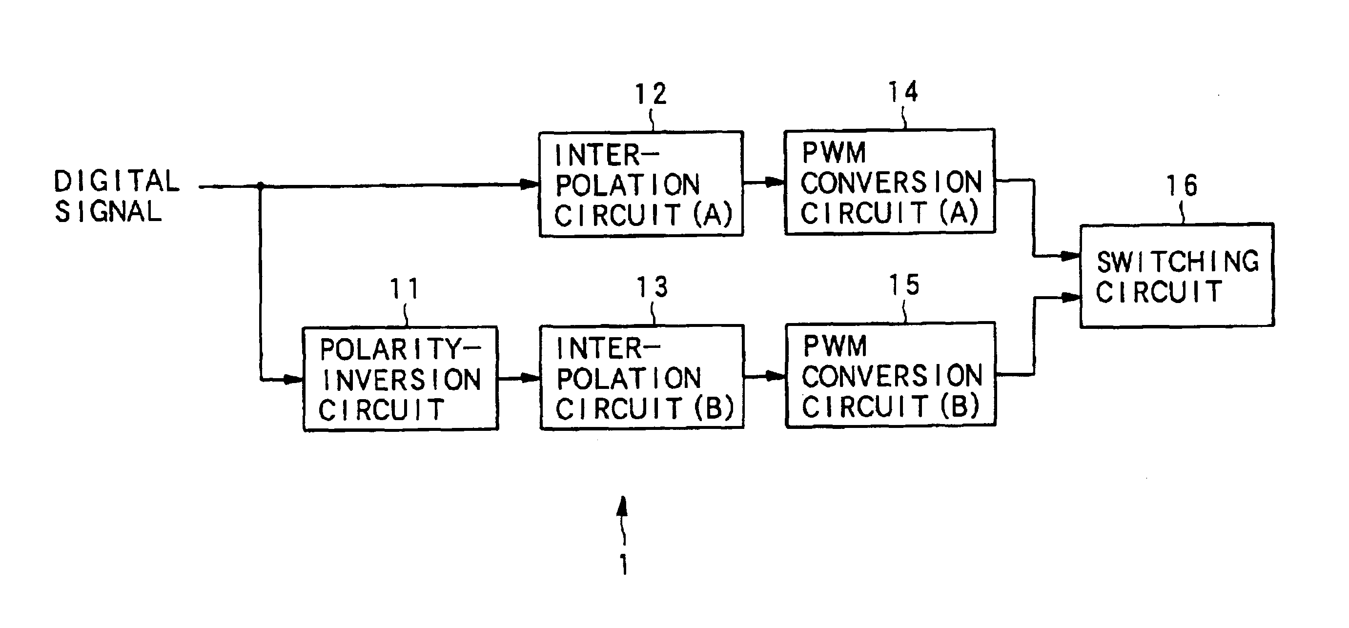
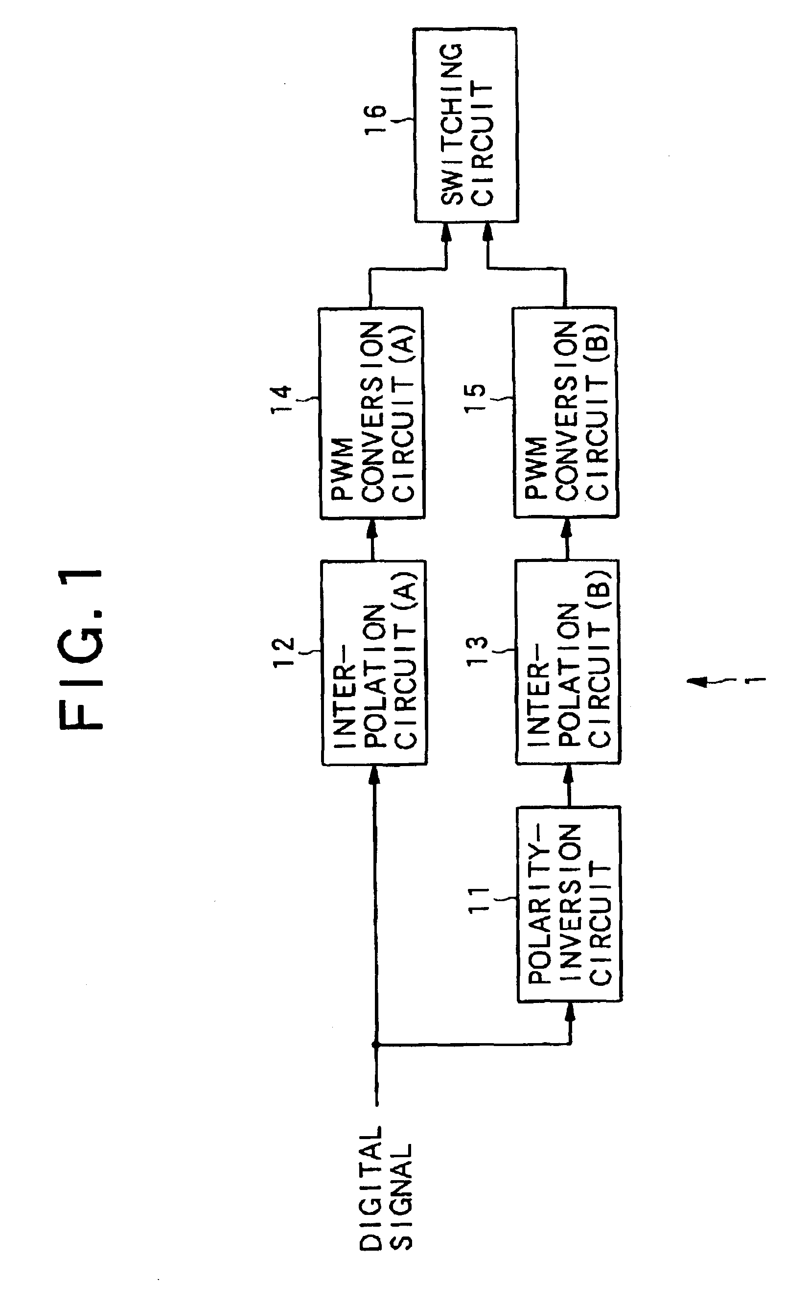
FIG. 1 is a block diagram showing the construction of the digital signal conversion apparatus of a first embodiment of the invention.

As shown in FIG. 1, the digital signal conversion apparatus 1 of this embodiment comprises: a polarity-inversion circuit 11 that inverts the input digital signal; an interpolation circuit (A) 12 that performs interpolation (described later) of the input digital signal; an interpolation circuit (B) 13 that performs interpolation (described later) of the inverted digit...

embodiment 2

(Embodiment 2)

Next, a second embodiment of the digital signal conversion apparatus of this invention will be explained by using FIG. 12 to FIG. 14.

In this embodiment, a digital signal conversion apparatus drives load using a three-value PWM signal, and together with improving the accuracy of approximation by interpolation and reducing non-linear distortion, it improves power efficiency since the output is zero when the input digital signal is zero, and furthermore it has little quantization noise in the audible range.

FIG. 12 is a block diagram showing the construction of the digital signal conversion apparatus of this second embodiment of the invention.

As shown in FIG. 12, the digital signal conversion apparatus of this embodiment comprises: a over-sampling circuit 21 that samples the input digital signal at high frequency; a polarity-inversion circuit 22 that inverts the polarity of the digital signal sampled by the over-sampling circuit 21; an interpolation circuit (A) 23 that per...


PUM


Abstract

The digital signal conversion apparatus comprises: an over-sampling circuit that samples the input digital signal at high frequency; a polarity-inversion circuit that inverts the polarity of the sampled digital signal; interpolation circuit (A) and interpolation circuit (B) that perform interpolation of each respective digital signal; noise-shaping circuit (A) and noise-shaping circuit (B) that perform noise shaping on the interpolated signals; PWM conversion circuit (A) and PWM conversion circuit (B) that perform PWM conversion on the noise-shaped signals; and a switching circuit for driving a load based on the PWM signals from PWM conversion circuit (A) and PWM conversion circuit (B).

Description

BACKGROUND OF THE INVENTION1. Field of the InventionThis invention relates to a digital signal conversion apparatus and digital signal conversion method that performs Pulse Width Modulation (PWM) on an input digital signal and converts it to an analog signal.2. Description of the Related ArtOne typical well-known method used by digital-to-analog converters for converting an input digital signal to an analog signal is the so-called PWM method, which converts an input digital signal to a PWM waveform and then converts that to an analog signal. The PWM method is also used in digital amps (D-class amp) that drive loads such as speakers or the like based on the input signal. The PWM of a digital signal (hereafter referred to as simply digital PWM) inevitably generates non-linear distortion.Conventionally, 2-value PWM in which the PWM waveform takes the two values +1 and −1, and 3-value PWM in which the waveform takes the three values +1, 0 and −1 have been known as PWM modulation methods...

Claims


Application Information

Patent Timeline
Patent Type & Authority Patents(United States)
IPC IPC(8): H03M5/00H03M5/08H03M1/82H03M3/02
CPCH03M5/08H03M1/822
Inventor KOMAMURA, MITSUYAYAMAUCHI, KEIICHI
Owner PIONEER CORP
Why Eureka
Try Eureka