Image display apparatus

Inactive Publication Date: 2005-03-29
CANON KK
View PDF6 Cites 48 Cited by
  • Summary
  • Abstract
  • Description
  • Claims
  • Application Information

AI Technical Summary

Benefits of technology

In attaining the above object and according to the present invention, there is provided an image display apparatus includinga display panel having plural rows of wiring and plural columns of wiring, and image forming devices connected with the rows and columns of wiring and arranged in a matrix,scan means for selectively scanning the rows of wiring one by one, andmodulation means connected with the columns of wiring, the image display apparatus comprising:adjusted image data c

Problems solved by technology

Further, the adjustment of image data may cause ov

Method used


Image

  • Image display apparatus
  • Image display apparatus
  • Image display apparatus

Examples


first embodiment

(First Embodiment)

(General Outline)

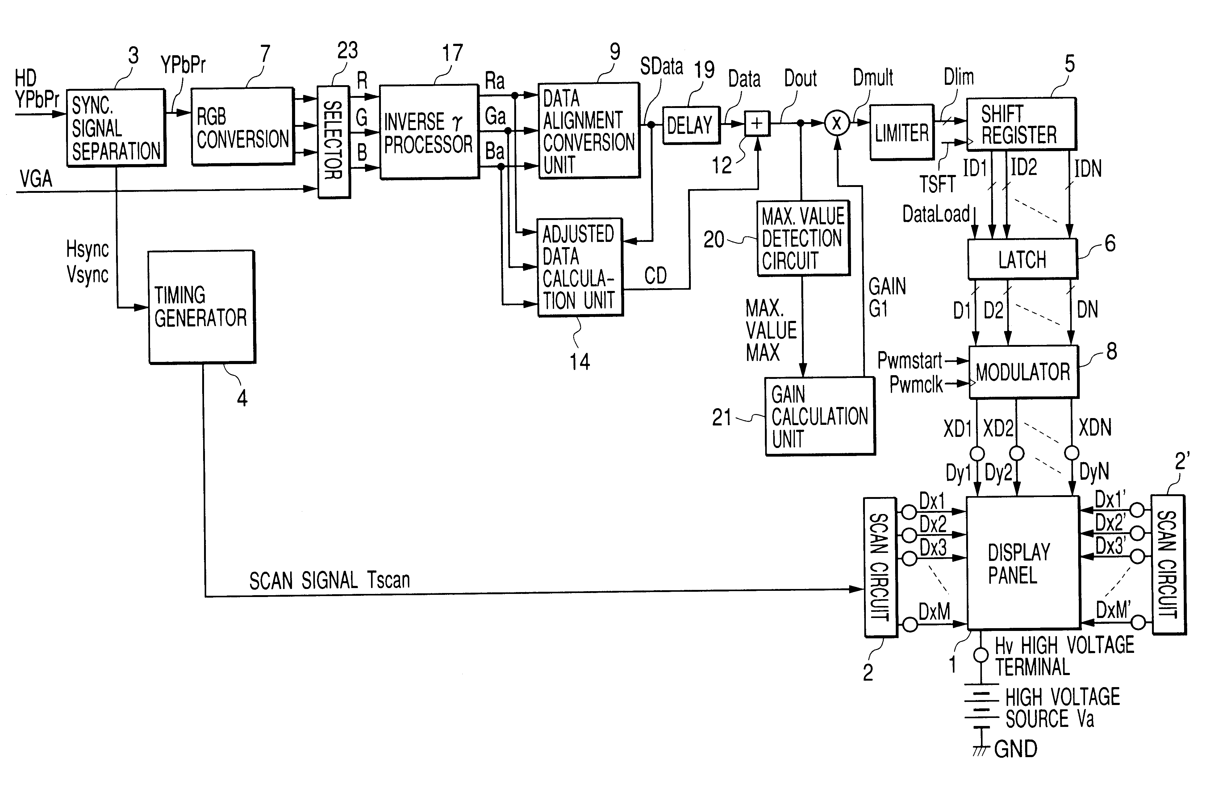
In a display apparatus using SCEs arranged in a simple matrix, current flowing into scan wiring and resistance of the scan wiring cause a voltage drop, and hence degradation of display images. To avoid this, the image display apparatus according to the embodiment of the present invention is provided with a processing circuit that properly compensates for the influence on the display images of voltage drop over the scan wiring. Further, in the embodiment, the processing circuit can be realized in a relatively small circuit configuration.

An adjustment circuit predictively calculates, according to input image data, the degradation of display images due to voltage drop to determine adjusted data for correcting the degradation so that the input image data will be adjusted.

The inventors have carefully studied the following type of image display apparatus as the image display apparatus in which such an adjustment circuit is incorporated.

The following will...

second embodiment

(Second Embodiment)

In the first embodiment, the maximum value of adjusted image data is detected to calculate such gain that the maximum value will correspond to the maximum value in the input range of the modulator. The adjusted image data is multiplied by the gain to prevent the occurrence of overflow.

In contrast, in the second embodiment, although the maximum value of adjusted image data is detected in the same manner, the size of image data before adjusted is so limited that the maximum value will correspond to the maximum value in the input range of the modulator.

In other words, the gain and image data already inputted are multiplied together to narrow down the amplitude range and hence prevent the occurrence of overflow.

Referring now to FIG. 25, overflow processing according to the embodiment will be described.

Shown in FIG. 25 are multipliers 22R, 22G, and 22B, the data alignment conversion unit 9, the sift register 5 for one line of image data, the latch circuit 6 for one lin...

third embodiment

(Third Embodiment)

In the first embodiment, reference values of discrete image data are set for input image data, and reference points are set on the row wiring, so that adjusted data is calculated at each reference point for the image data the size of which takes a corresponding reference value.

Further, the adjusted data discretely calculated is interpolated to calculate adjusted data according to the horizontal display position and size of the input image data, so that the adder adds the image data and the adjusted data calculated, thus making a correction to the image data.

On the other hand, a configuration shown in FIG. 26 can also makes a correction to the image data in the same manner. Referring to FIG. 26, the third embodiment will be described below.

Points in which FIG. 26 differs from FIG. 11 are that the adjusted data calculation unit 14 and the adder 12 are eliminated, and a discrete adjusted image data calculation unit 14a and an adjusted image data interpolation circuit ...


PUM


Abstract

The present invention is to provide an image display apparatus capable of properly correcting or adjusting, with small-scale hardware, variations in drive conditions due to electric resistance of matrix wiring on a display panel. The image display apparatus includes an adjusted image data calculation unit 14 for calculating adjusted image data as image data that has been compensated for the influence of voltage drop caused by resistance of at least the row wiring and a scan unit. The image display apparatus also includes an amplitude adjustment unit having a function for adjusting the amplitude of adjusted image data Dout, and a modulator 8 the takes in the adjusted image data with the amplitude adjusted and outputs a modulation signal to the column wiring.

Description

BACKGROUND OF THE INVENTION1. Field of the InventionThe present invention relates to an image display apparatus provided with image forming devices arranged in a matrix. For example, the present invention is applied to a television receiver or a display apparatus for receiving television signals or display signals from a computer or the like to display images using a display panel that is provided with a plurality of surface conduction devices arranged in a matrix and a fluorescent screen receiving electron irradiation and emitting light. In particular, the present invention relates to image data adjustment means for correcting a drop in drive voltage due to electric resistance of the matrix wiring or the like on the display panel, and digital image data processing means having amplitude adjustment means for controlling the amplitude of the adjusted image data.2. Related Background ArtConventionally, as image display apparatuses of this type, Japanese Patent Application Laid-Open No...

Claims


Application Information

Patent Timeline
IPC IPC(8): G09G3/22G09G3/20
CPCG09G3/22G09G3/2014G09G2320/0223G09G2360/144G09G2320/0285G09G2320/0606G09G2320/0626G09G2320/0276
Inventor SAGANO, OSAMUABE, NAOTOINAMURA, KOHEISAITO, HIROSHIIKEDA, TAKESHI
Owner CANON KK
Why Eureka
Try Eureka