Liquid crystal device and electronic apparatus

a technology of electronic equipment and liquid crystal, which is applied in the direction of instruments, propulsion parts, packaging, etc., can solve problems such as reducing contras

Inactive Publication Date: 2005-03-29
138 EAST LCD ADVANCEMENTS LTD
View PDF16 Cites 19 Cited by
  • Summary
  • Abstract
  • Description
  • Claims
  • Application Information

AI Technical Summary

Benefits of technology

In view of the above, an object of the present invention is to provide a reflective or transflective liquid crystal device capable of displaying a high-brightness and high-contrast image without producing double images or dull images due to parallax, and also an electronic apparatus using such a liquid crystal device.
According to the third electronic apparatus of the present invention, it is possible to realize various types of electronic apparatuses using a transflective liquid crystal device or a transflective color liquid crystal device capable of displaying, in both a reflective displaying mode and a transmissive fashion, a high-brightness and high-contrast image including no ghost and no dull images due to parallax. The first to third electronic apparatuses can display a high-quality image without being affected by ambient light regardless of whether it is used in a light or dark environment.

Problems solved by technology

If such a part of light is reflected toward the liquid crystal layer, a defect known as a bright defect (white defect) occurs, which results in a reduction in the contrast.

Method used


Image

  • Liquid crystal device and electronic apparatus
  • Liquid crystal device and electronic apparatus
  • Liquid crystal device and electronic apparatus

Examples


first embodiment

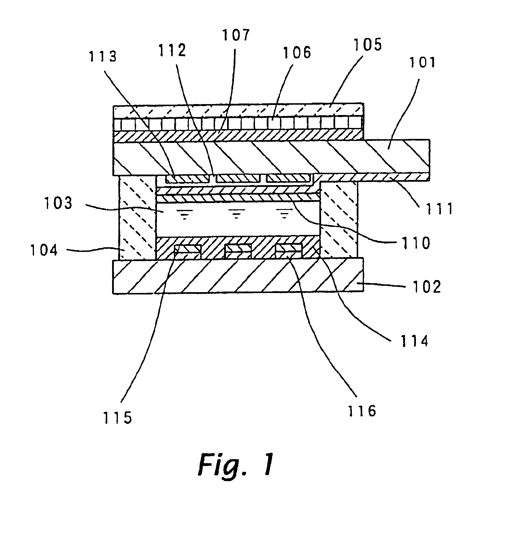
A first embodiment of a liquid crystal device according to the present invention is described below with reference to FIGS. 1-2b. FIG. 1 is a longitudinal sectional view schematically illustrating the structure of the first embodiment of the liquid crystal device according to the present invention. Although this embodiment is basically concerned with a passive matrix type liquid crystal device, the structure disclosed herein may also be applied to other types of liquid crystal devices such as an active matrix type device, a segment type device, etc.

In this reflective liquid crystal device of the first embodiment, as shown in FIG. 1, there is provided a liquid crystal cell including a liquid crystal layer 103 sealed between two transparent substrates 101 and 102 and within a frame-shaped sealing member 104. The liquid crystal layer 103 is formed of a nematic liquid crystal with a particular twisted angle. A color filter 113 is formed on the inner surface of the upper transparent subs...

second embodiment

A second embodiment of a liquid crystal device according to the present invention is described below with reference to FIG. 3. FIG. 3 is a longitudinal sectional view illustrating the structure of the liquid crystal device according to the second embodiment of the invention. This third embodiment is similar in construction to the first embodiment described above except that transparent electrodes and reflective films are formed in a different structure. In FIG. 3, similar constituent elements to those in the first embodiment described above with reference to FIG. 1 are denoted by similar reference numerals, and thereby they will be omitted.

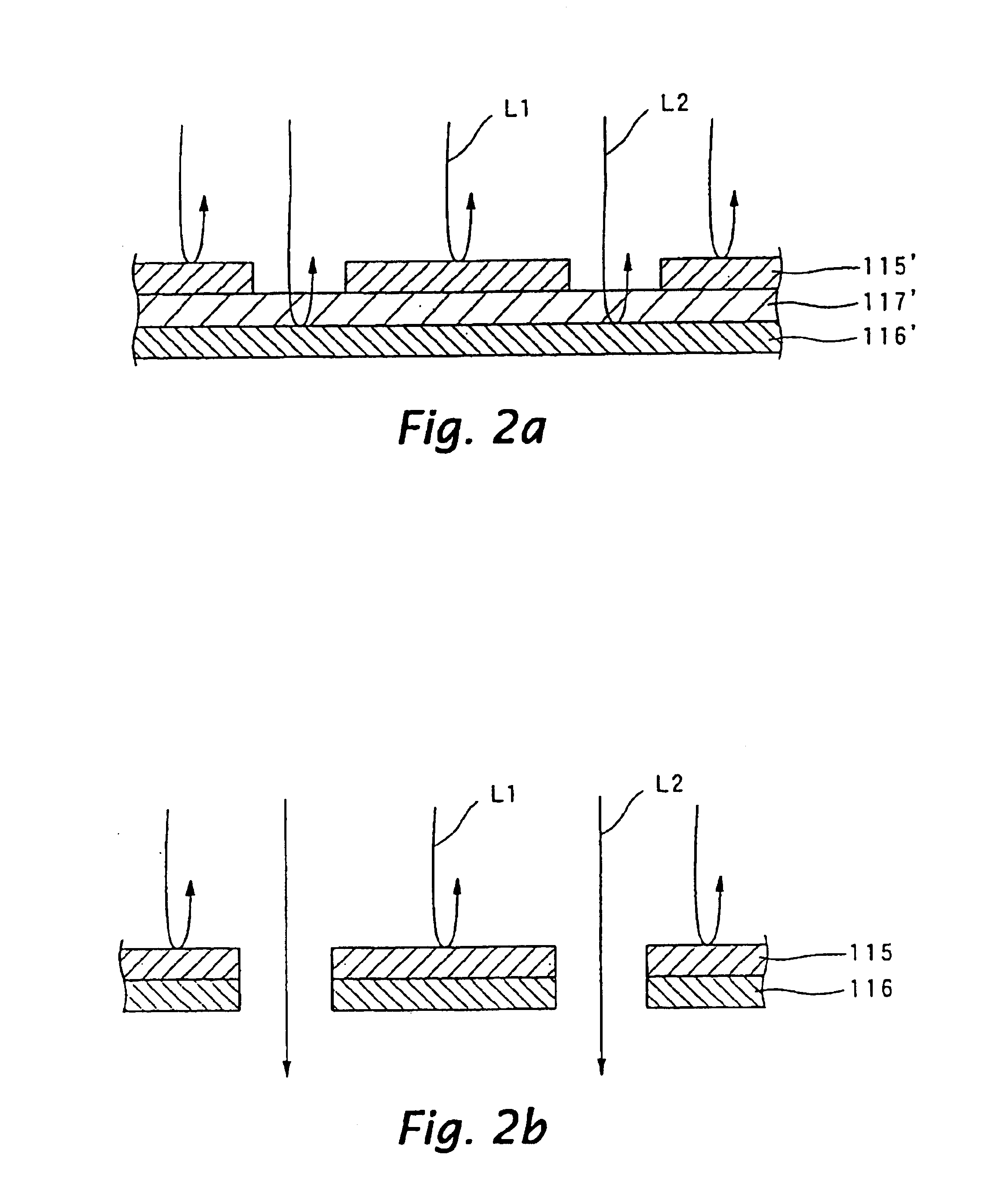
In th e reflective liquid crystal device of the second embodiment, as shown in FIG. 3, an insulating film 117 is formed between each reflective film 116 and each transparent electrode 115. The other parts are similar to those of the first embodiment. An example of the process of forming the insulating film 117 is described below.

First, reflective ...

third embodiment

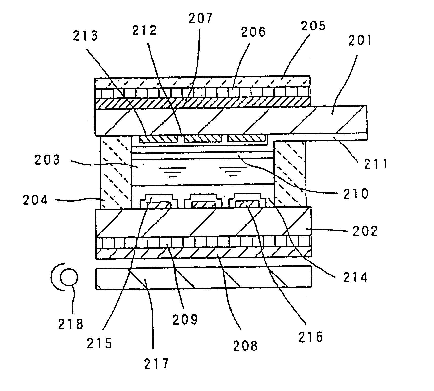
A third embodiment of a liquid crystal device according to the present invention is described below with reference to FIGS. 4 to 6. FIG. 4 is a longitudinal sectional view schematically illustrating the structure of the third embodiment of the liquid crystal device according to the present invention. Although this embodiment is basically concerned with a passive matrix type liquid crystal device, the structure disclosed herein may also be applied to other types of liquid crystal devices such as an active matrix type device, a segment type device, etc.

In the transflective liquid crystal device of the third embodiment, as shown in FIG. 4, there is provided a liquid crystal cell including a liquid crystal layer 203 sealed between two transparent substrates 201 and 202 and within a frame-shaped sealing member 204. The liquid crystal layer 203 is formed of a nematic liquid crystal with a particular twisted angle. A color filter 213 is formed on the inner surface of the upper transparent ...


PUM

PropertyMeasurementUnit
thicknessaaaaaaaaaa
thicknessaaaaaaaaaa
current densityaaaaaaaaaa

Abstract

Ambient light incident upon a polarizer 105 passes through a liquid crystal layer 103 and is then reflected by reflective films 116 via transparent electrodes 115. The reflected light passes again through the liquid crystal layer 103 and the polarizer 105 and is output to the outside thereby displaying an image in a reflective displaying mode. The reflective films 116 are disposed at locations corresponding to the respective transparent electrodes 115 such that they are spaced from each other. In this structure, some ambient light passes through the spaces between adjacent transparent electrodes 115, however, such light is not reflected by the reflective films 116 toward the outside and thus a reduction in contrast due to such reflection is prevented.

Description

TECHNICAL FIELDThe present invention relates to the field of liquid crystal devices, and more particularly to the structure of liquid crystal devices of reflective type and of transflective type, and also to an electronic apparatus using such a liquid crystal device.BACKGROUND ARTVarious types of liquid crystal devices are known in the art. They include a reflective liquid crystal device which displays an image by reflecting ambient light through a liquid crystal by reflecting means provided in the device, a transmissive type liquid crystal device in which light emitted from a light source provided in the device is passed through a liquid crystal and output to the outside thereby forming an image, and a transflective liquid crystal device capable of switching its displaying mode between reflective and transmissive modes.Of these liquid crystal devices, reflective liquid crystal devices can operate with very low power consumption because they need no light source. Because of such an ...

Claims


Application Information

Patent Timeline
Patent Type & Authority Patents(United States)
IPC IPC(8): G02F1/1335G02F1/13B65D51/00B60K15/04G02F1/13357G02F1/13363
CPCG02F1/133553G02F1/133555G02F1/13363G02F1/133615G02F2413/02G02F2201/123G02F2203/09G02F1/1335
Inventor MAEDA, TSUYOSHIOKUMURA, OSAMUOKAMOTO, EIJISEKI, TAKUMI
Owner 138 EAST LCD ADVANCEMENTS LTD
Why Eureka
Try Eureka