
Method and apparatus for providing feeder cable insertion loss detection in a transmission system without interfering with normal operation

a transmission system and feeder cable technology, applied in the field of performance monitoring of communication systems, can solve the problems of tremendous impact on revenues and profits, increase in the measurable loss (ssub>21/sub>) of the feeder coax cable, and customer traffi

Inactive Publication Date: 2005-03-29
NOKIA SOLUTIONS & NETWORKS OY
View PDF17 Cites 45 Cited by
  • Summary
  • Abstract
  • Description
  • Claims
  • Application Information

AI Technical Summary

Benefits of technology

Another aspect of the present invention is that the frequency of the selected signal for injection causes the narrowband device to appear to the selected signal for injection as a short.
A transmission system providing operating signals to a narrowband device over a cable according to the present invention includes an injection coupler disposed at a position relative to the cable distal from the narrowband device, the coupler injecting a signal onto the cable, the injected signal being selected to have a frequency and power that does not interfere with the operating signals and which causes the signal to reflect back from the narrowband device, a forward port, coupled to the cable proximate the injection coupler, the forward port allowing an amplitude of the injected signal to be measured and a reference port, coupled to the cable proximate the injection coupler, the reference port allowing an amplitude of the reflected signal to be measured.

Problems solved by technology

Thus, any reduction in customer traffic due to network problems has a tremendous impact on revenues and profits.
One problem encountered by cellular operators is an increase in the measurable loss (S21) of the feeder coax cable.
The symptoms of loss via a deteriorated S21 typically involves a reduction in Base Transceiver Station (BTS) traffic, an increase in the number of dropped calls and an increase in subscriber complaints.
Typical causes for an increase in feeder cable loss include water in the feeder cable, mechanical stress placed on the cable during instillation, temperature cycling of the cable, connector failure and the effects of UV light on the cable.
To make matters worse this type of problem occurs gradually.
This makes the detection of this problem much more difficult.
However, this method allows only for the detection of an impedance change in the cable (S11 ) i.e. if the cable is no longer presented 50Ω to the BTS output connector or not.
Still, an increase in the insertion loss of a feeder cable may occur with no or very little change in the cables impedance, and therefore no indication of a change in the performance of the feeder cable will be detected by current systems and methods for measuring the performance of feeder cables.

Method used


Image

  • Method and apparatus for providing feeder cable insertion loss detection in a transmission system without interfering with normal operation
  • Method and apparatus for providing feeder cable insertion loss detection in a transmission system without interfering with normal operation
  • Method and apparatus for providing feeder cable insertion loss detection in a transmission system without interfering with normal operation

Examples


Embodiment Construction

In the following description of the exemplary embodiment, reference is made to the accompanying drawings which form a part hereof, and in which is shown by way of illustration the specific embodiment in which the invention may be practiced. It is to be understood that other embodiments may be utilized as structural changes may be made without departing from the scope of the present invention.

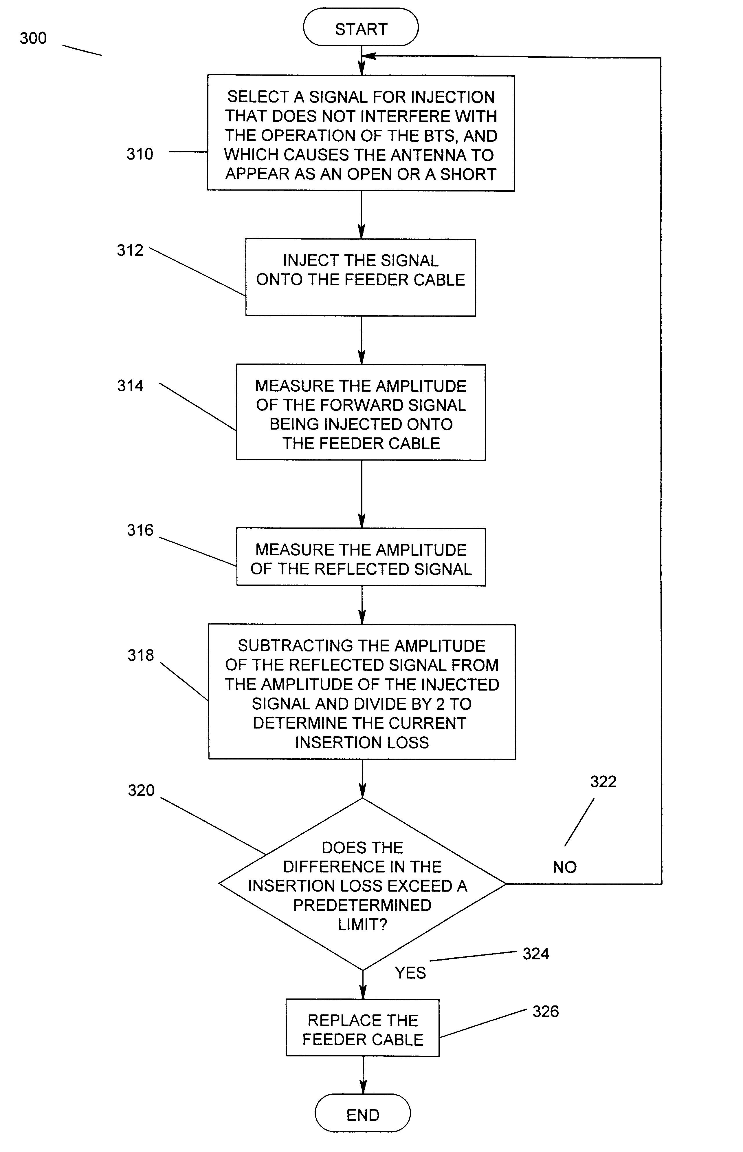
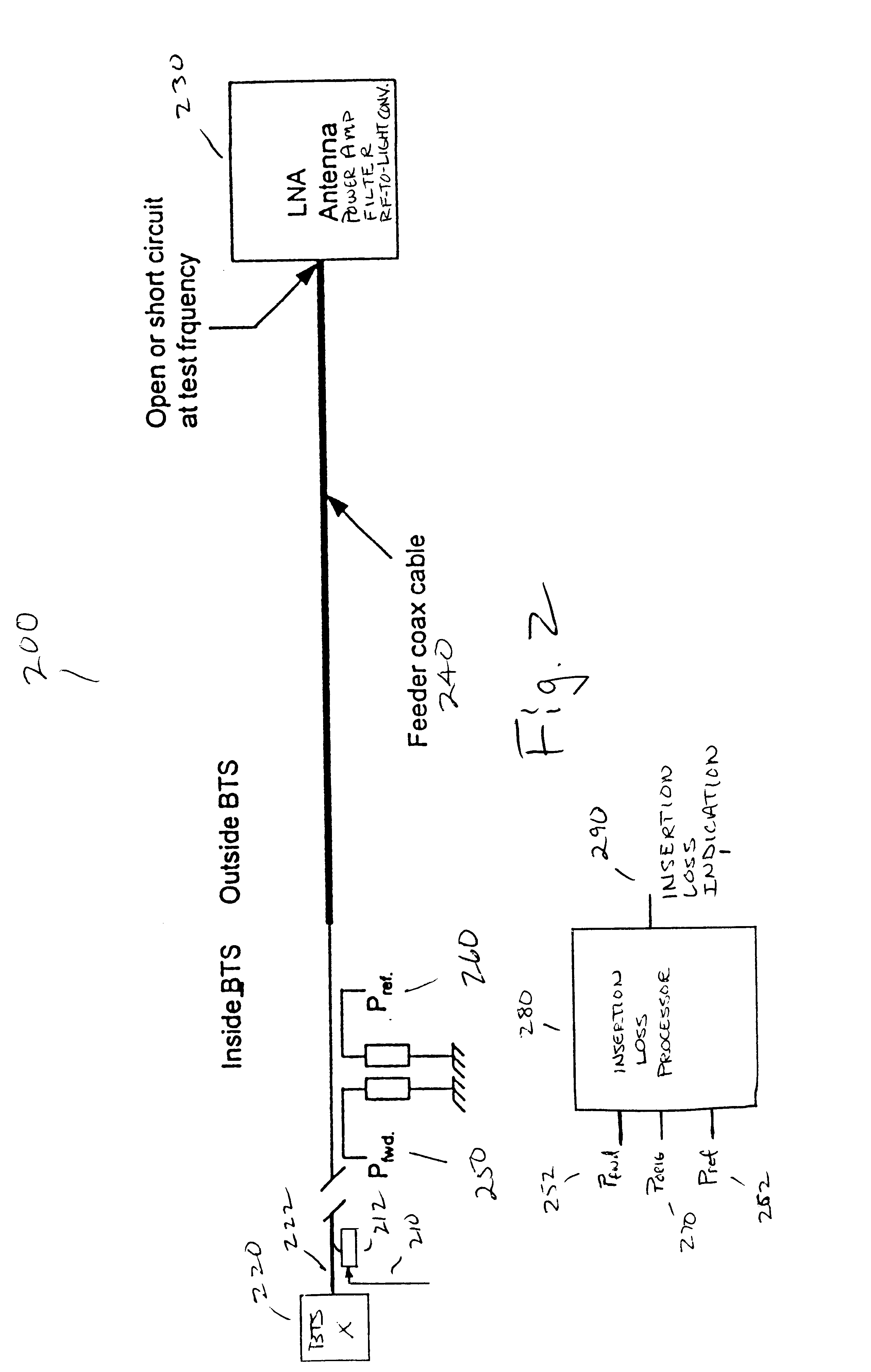
The present invention provides a system and method for detecting a change in the performance characteristics of feeder cables by monitoring the feeder cables for a change in the insertion loss of the feeder cables.

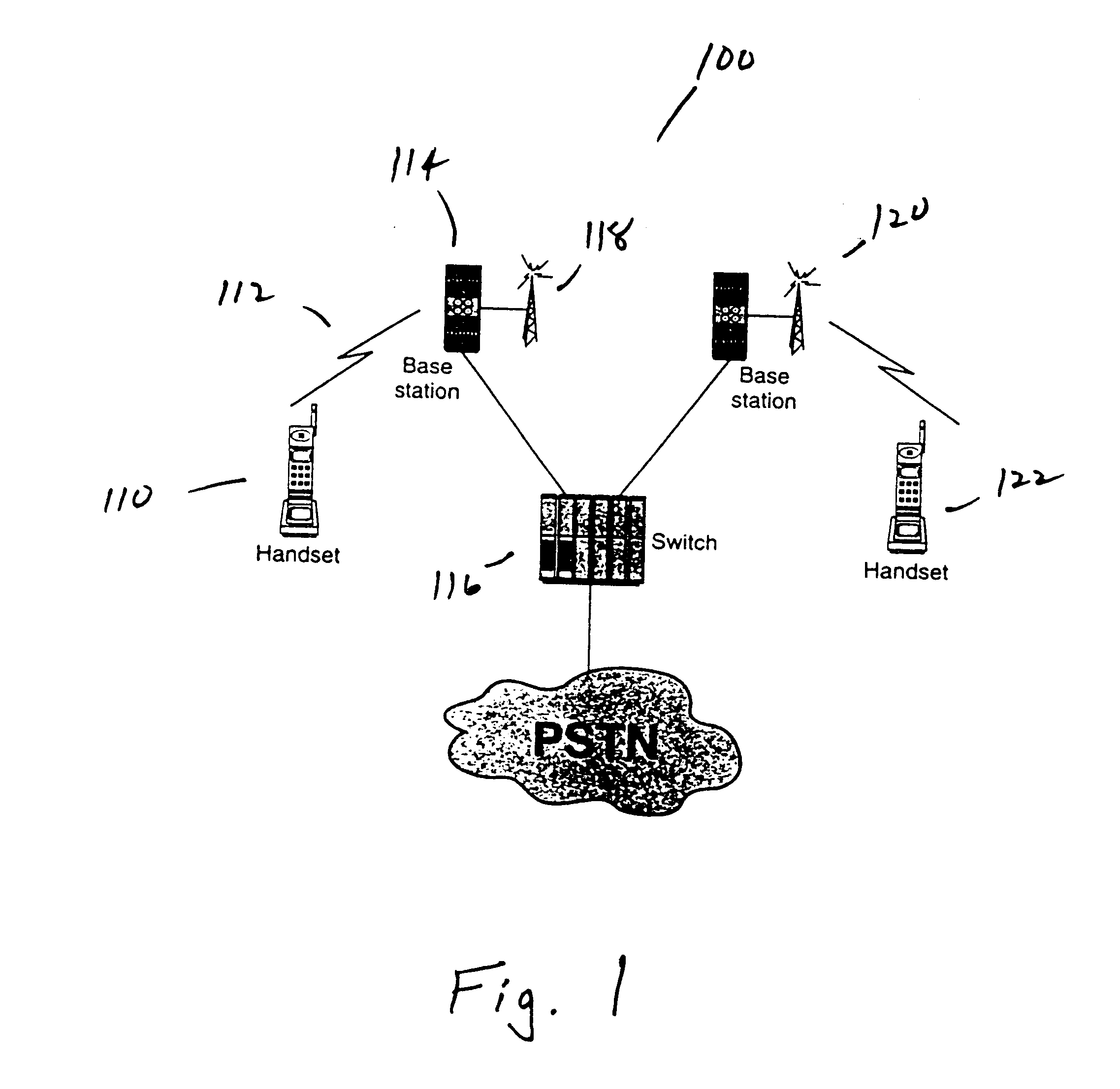
FIG. 1 illustrates a wireless telecommunication system 100. This system can be broken down to blocks as shown in FIG. 1. The human voice fed to the microphone of a mobile station or handset 110 is transmitted through the atmosphere 112 to the base station 114. From the base station 114, the signal is routed to a switching center 116 or rebroadcast 118. Similarly, at the network end the...


PUM


Abstract

A method and apparatus for measuring a change in the insertion loss of a transmission line in a communication system is disclosed. The method provides feeder cable insertion loss detection in a transmission system without interfering with normal operation. The method includes injecting a non-interfering signal at a predetermined frequency onto a cable providing normal operating signals to a narrowband device at a predetermined frequency, measuring the amplitude of the injected signal, measuring the amplitude of a reflected signal, the injected signal being reflected by the narrowband device and processing the amplitude of the injected signal and the amplitude of the reflected signal to derive a current insertion loss for the cable. In addition, the method further includes comparing the current insertion loss to a prior insertion loss and determining the cable to be defective when the current insertion loss differs from the prior insertion loss by a predetermined amount and replacing the cable when the current insertion loss differs from the prior insertion loss by the predetermined amount. The injecting further includes selecting a signal for injection having a frequency and power that does not interfere with the normal operating signals and which causes the signal to reflect back from the narrowband device. The frequency of the selected signal for injection causes the narrowband device to appear to the selected signal for injection as a short or an open. The narrowband device is an antenna, a low noise amplifier, a power amplifier, a filter or a RF-to-light converter for a fiber optic distribution network.

Description

BACKGROUND OF THE INVENTION1. Field of the InventionThis invention relates in general to the performance monitoring of communication systems, and more particularly to a method and apparatus for measuring a change in the insertion loss of a transmission line in a communication system.2. Description of Related ArtCellular communication systems are experiencing tremendous growth in the global communication market place. This growth is fueling many research programs and expanding the technology opportunities for all manufacturers of cellular equipment.To attract customers and obtain a larger market share, cellular providers are pushing features enabled by the system's purely digital nature, such as Caller ID and short messaging, a paging equivalent. To further obtain a larger market share, cellular providers have turned to reducing the cost of air time. Cutting prices can take many forms. For example, vendors can give more free minutes per month, charge less for additional minutes, char...

Claims


Application Information

Patent Timeline
IPC IPC(8): H04Q7/34H04W24/00
CPCH04W24/00
Inventor WRIGHT, JONATHAN
Owner NOKIA SOLUTIONS & NETWORKS OY
Features
  • Generate Ideas
  • Intellectual Property
  • Life Sciences
  • Materials
  • Tech Scout
  • Unparalleled Data Quality
  • Higher Quality Content
  • 60% Fewer Hallucinations
Learn More