Speed filter

a technology of speed filter and internal combustion engine, which is applied in the direction of speed sensing governor, electric control, instruments, etc., can solve the problems of over-limiting speed, affecting the stability of drive system, and amplitude of torsional oscillation, so as to reduce the influence of manufacturing tolerances of odometers, reduce the influence of speed detection loop dynamics, and reduce the influence of odometer manufacturing tolerances

Inactive Publication Date: 2005-03-29
MOTOREN & TURBINEN UNION FRIEDRICHSHAFEN GMBH
View PDF11 Cites 6 Cited by
  • Summary
  • Abstract
  • Description
  • Claims
  • Application Information

AI Technical Summary

Benefits of technology

In accordance with the invention, the speed filter includes a calculation rule with which the torsional vibration of the ith order is eliminated completely or at least in part. The torsional oscillation of the 0.5th order, for example, is eliminated completely through a calculation rule that provides that the current tooth timing value is added to the tooth timing value of one revolution earlier. Contrary to the 2 revolution filter from the prior art, this results in the advantage that the actual speed value is already available at an earlier time. Speed detection is thus quicker compared to the prior art. In other words, the dynamics of the speed control loop are increased without endangering the stable behavior of the drive system. In order to minimize the influence of ...

Problems solved by technology

The problem with such a control loop is that torsional oscillations, which are superimposed on the controlled variable, can be reinforced by the speed regulator.
When starting the drive system the amplitudes of the torsional oscillations can become so large due ...

Method used


Image

  • Speed filter
  • Speed filter
  • Speed filter

Examples


Embodiment Construction

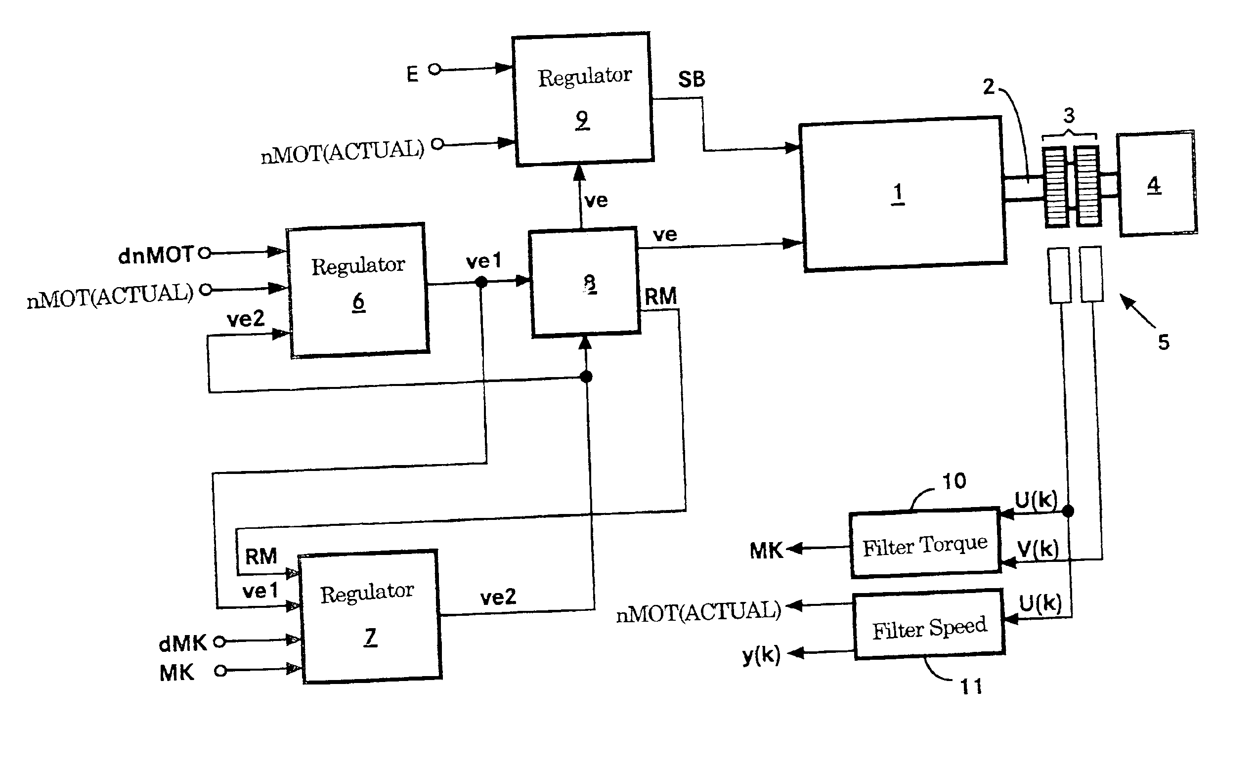
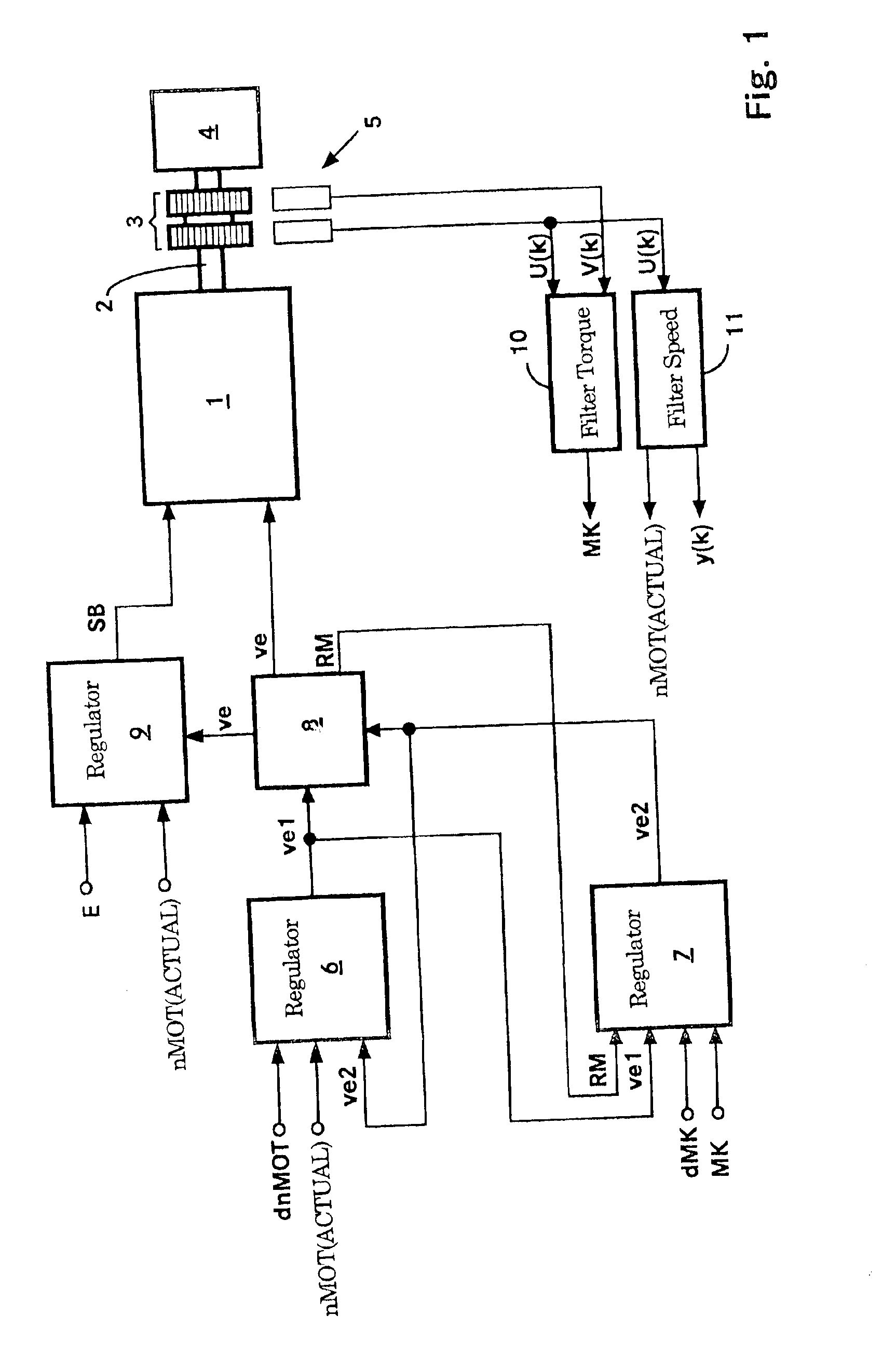
FIG. 1 depicts a block diagram of the control system of the internal combustion engine 1 with coupled control loop structure. Represented are: a speed regulator 6, an engine torque regulator 7, a selecting device 8, an injection start regulator 9 and the internal combustion engine 1 with the injection system, for example, a common rail system. The internal combustion engine 1 drives an engine load 4, for example, a generator or a ship's propulsion, via the shaft 2. On the shaft 2 gear wheels 3 are arranged. The tooth timing values U(k) and V(k) of the gear wheels 3 are detected by the speed sensors 5. The current tooth timing value U(k) is used to calculate a filtered tooth timing value y(k) or accordingly an actual speed nMOT(ACTUAL) by means of a speed filter 11. The engine torque MK on the output of the internal combustion engine 1 is determined with the torque filter 10. The actual engine speed nMOT(ACTUAL) is used as an input variable for the speed regulator 6 and the injection...


PUM


Abstract

The invention relates to a speed filter for an internal combustion engine. Said filter contains a calculation rule (BV(i)), which is used to completely or partially eliminate a speed oscillation of the i-th order, thus improving the dynamics and the robustness of the speed control loop.

Description

CROSS-REFERENCE TO RELATED APPLICATIONSThis application claims the priority of German application 101 22 517.2, filed May 9, 2001, which was filed as International Application No. PCT / EP02 / 04922, on May 4, 2002, the disclosure of which is expressly incorporated by reference herein.FIELD OF THE INVENTIONThe invention relates to a speed filter for an internal combustion engine whose speed is detected in the form of the tooth timing of a shaft. The tooth timing values are used to determine a filtered tooth timing value by means of a speed filter, corresponding to the actual speed value.BACKGROUND OF THE INVENTIONAn internal combustion engine that is provided as a generator drive is conventionally supplied to the end user without a clutch and generator. The clutch and the generator are only mounted at the end customer's location. In order to ensure a consistent rated frequency for power supply into the network, the internal combustion engine is operated in a speed control loop. This det...

Claims


Application Information

Patent Timeline
IPC IPC(8): F02D31/00F02D41/34G01P3/42G01P3/489F02D45/00
CPCF02D31/007F02D41/0097G01P3/489F02D2041/1418F02D2041/1432F02D2041/1409
Inventor DOELKER, ARMIN
Owner MOTOREN & TURBINEN UNION FRIEDRICHSHAFEN GMBH
Why Eureka
Try Eureka