
Elevator installation with a measuring system for determining absolute car position

a technology of absolute car position and installation method, which is applied in the direction of elevators, instruments, transportation and packaging, etc., can solve the problems of reducing resolution capability, high cost, and noticeably more difficult reading off with decreasing length of code marks, and achieve the effect of reducing the possible expenditur

Inactive Publication Date: 2005-04-05
INVENTIO AG
View PDF12 Cites 40 Cited by
  • Summary
  • Abstract
  • Description
  • Claims
  • Application Information

AI Technical Summary

Benefits of technology

[0009]An object of the present invention is to provide an elevator with a measuring system for determining the absolute position of the elevator car, which enables a high-resolution in the position recognition over a long travel path of the elevator car with the smallest possible expenditure.

Problems solved by technology

However, reading-off becomes noticeably more difficult with decreasing lengths of the code marks, particularly in the case of high relative speeds.
However, multi-digit code words necessitate correspondingly complicated code reading devices and evaluating units and this is connected with high costs.
With increasing length of the individual code marks, however, the resolution capability diminishes.
This makes the production of a double-track code carrier expensive and moreover necessitates a time-consuming precise mounting.
In addition, the code reading device, in particular, of a double-track absolute position measuring system is of large construction, which is undesirable with respect to the limited shaft cross-sectional area available.
Furthermore, the travel speed in the case of double-track measuring systems is limited, which is felt to be limiting especially for elevators with large conveying heights.

Method used


Image

  • Elevator installation with a measuring system for determining absolute car position
  • Elevator installation with a measuring system for determining absolute car position
  • Elevator installation with a measuring system for determining absolute car position

Examples


Embodiment Construction

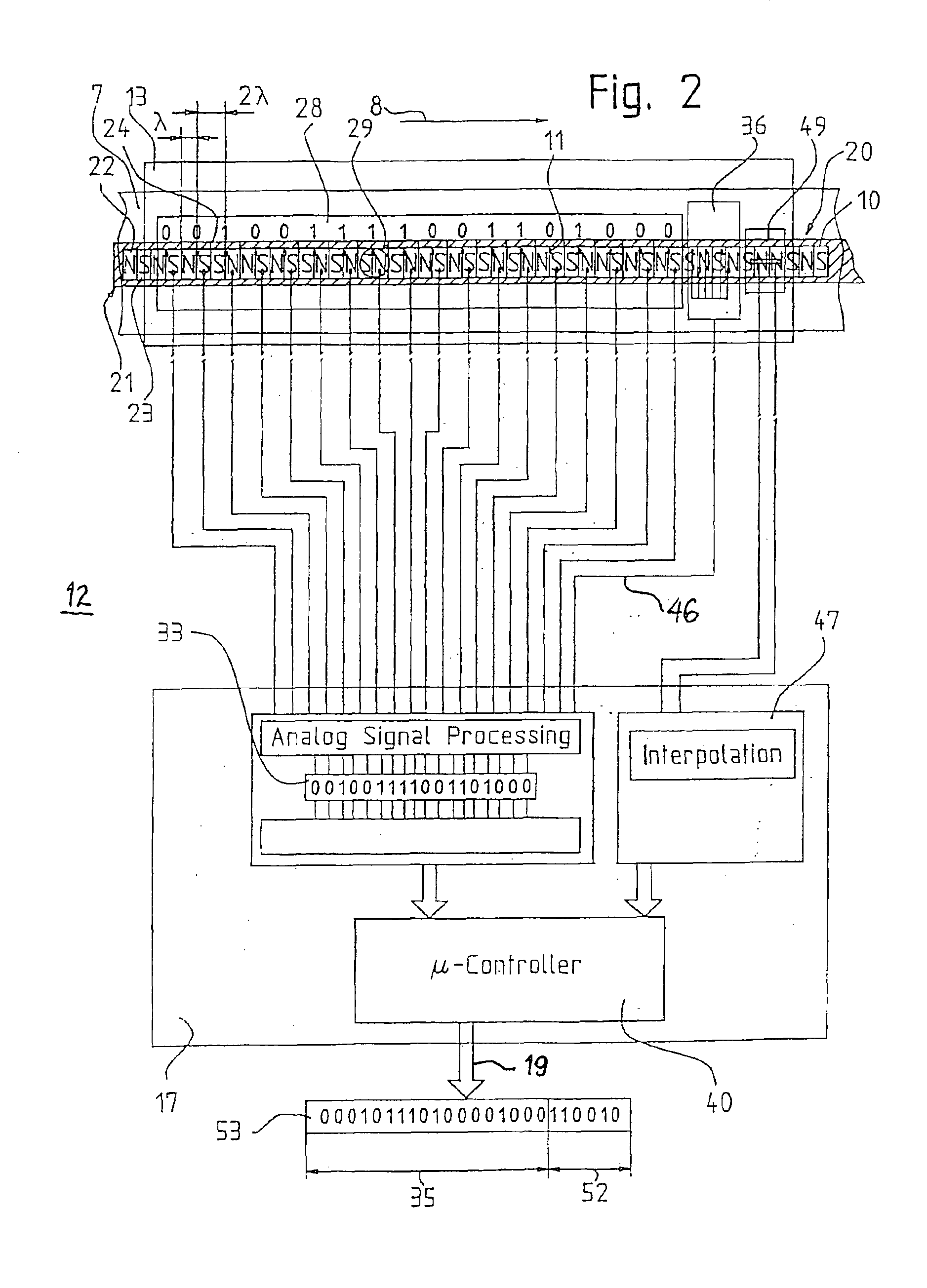
code reading pairs of the code reading sensor system shown in FIG. 2;

[0028]FIG. 5 is a waveform diagram showing an output signal generated by the interpolation unit shown in FIG. 2;

[0029]FIG. 6 is a waveform diagram showing an output signal of an MR angle sensor of the fine interpolation unit scanning of the magnetic field along the coded magnetic strip shown in FIG. 3;

[0030]FIG. 7 is a schematic illustration of a second variation of the code reading pairs of the code reading sensor system shown in FIG. 2; and

[0031]FIG. 8 is a schematic block diagram of a redundant construction of the measurement system as the basis of a comprehensive shaft information system according to the present invention.

DESCRIPTION OF THE PREFERRED EMBODIMENT

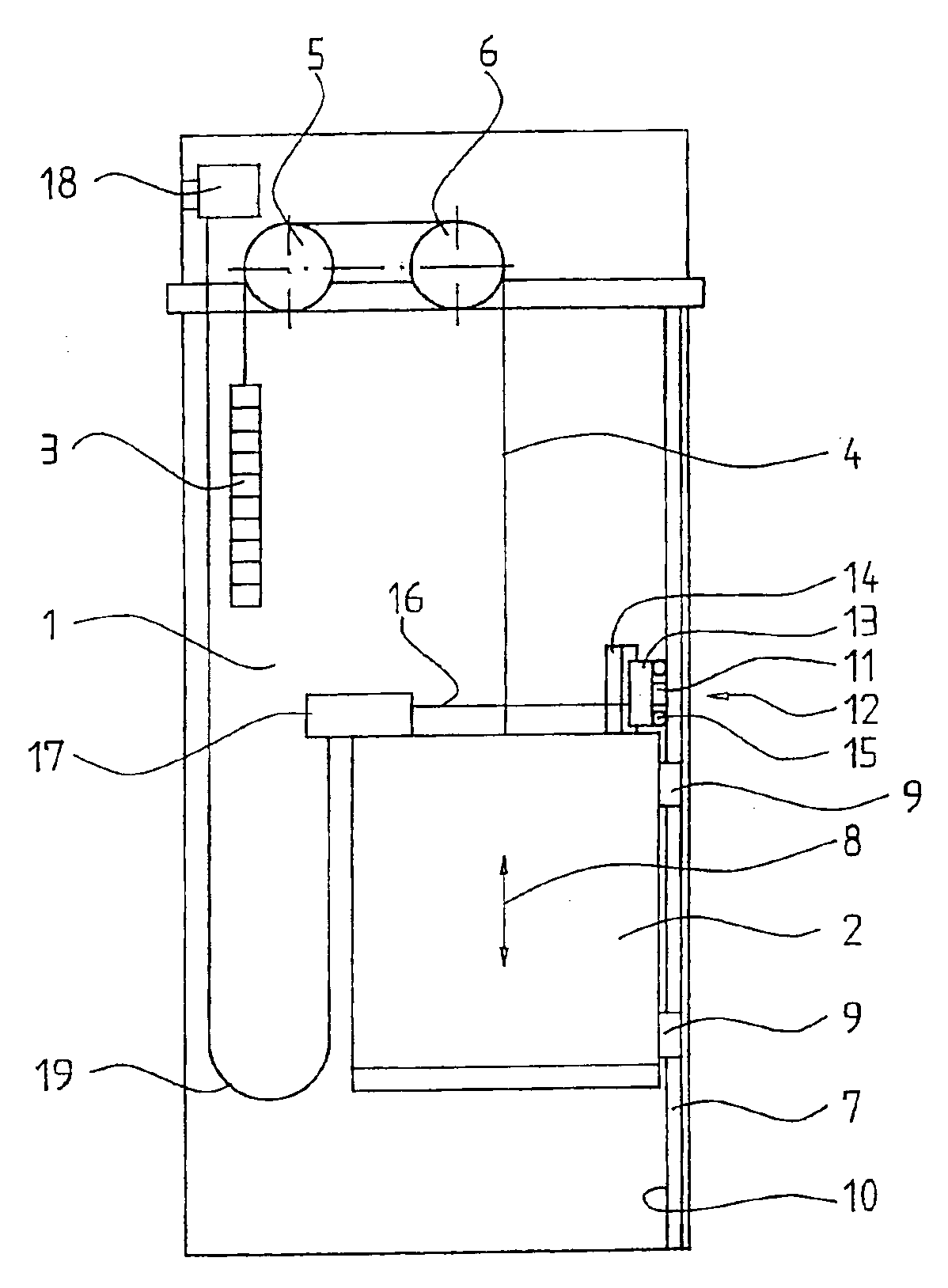
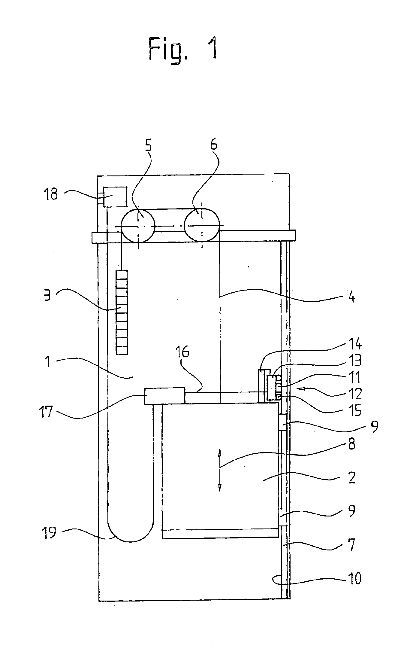
[0032]In an elevator installation —which is schematically illustrated in FIG. 1—with an elevator shaft 1, an elevator car 2 and a counterweight 3 are suspended at several support cables, of which a single support cable 4 is illustrated here as representat...


PUM


Abstract

An elevator car position measuring system includes a strip having a code mark pattern mounted near the elevator car and parallel to a travel direction, a code reading device mounted on the elevator car for contactless scanning of the code mark pattern and an evaluating unit connected to the code reading device for evaluating the scanned code mark pattern. A code word is formed by “n” successive code marks of the code mark pattern, a plurality of different ones of the code words are unambiguously arranged in an n-digit pseudo random sequence, the code words form a single-track of the code mark pattern and each of the code words represents an absolute car position. A floor sensor mounted on the elevator car detects position markings at floor levels along the travel direction and is connected to the evaluating units for evaluating the detected position markings against said scanned code words.

Description

[0002]This application is a Continuation of PCT / CH02 / 00406 filed July 22, 2002.BACKGROUND OF THE INVENTION[0003]The present invention relates to an elevator installation with a measuring system for determining the absolute car position of an elevator car movable along at least one guide rail.[0004]In elevators, the positional information is applied in coded form in stationary position along the entire travel path of the elevator car and is read off in coded form by means of a code reading device and passed on to an evaluating unit. The evaluating unit prepares the read-off coded positional information to be comprehensible by a control and derives therefrom data signals which are passed on to the elevator control as so-termed shaft data.[0005]An absolute measuring system with high resolution for determination of the relative position of two parts movable relative to one another is known from the German patent document DE 42 09 629 A1. In hitherto conventional manner, an absolute code...

Claims


Application Information

Patent Timeline
IPC IPC(8): B66B1/34G01B21/00B66B3/02B66B7/02B66B11/02
CPCB66B1/3492
Inventor BIRRER, ERICESSINGER, HEIKOMULLER, FRANK
Owner INVENTIO AG
Learn More