Wear measurement gauge for padeyes shackles and chains

Inactive Publication Date: 2005-04-05
SAUDI ARABIAN OIL CO
View PDF12 Cites 5 Cited by
  • Summary
  • Abstract
  • Description
  • Claims
  • Application Information

AI Technical Summary

Benefits of technology

A wear measurement device is disclosed which permits reliable and accurate measurements of wear and wear trends for fastening devices used in maritime and on-shore applications, such as chains, shackles, padeyes, anchor legs, and the like. The device of the invention

Problems solved by technology

Such fastening devices experience wear from frictional interaction between adjacent and/or abutting portions of the fastening devices, as well as, other eroding or corroding factors and sources such as oxidation, interaction with salt water, pollution, cleaning chemicals, etc.
For example, the wear of padeyes, shackles, and chains has caused problems in the past including the loss of anchor leg moorings in ship berths.
Because of such wear, erosion, and/or corrosion, potential damage and even the loss of berthed ships, as well as pollution and/or damage to adjacent facilities from break-away vessels, can be the cause of potentially high costs and severe safety breaches.
Necessary repairs and maintenance, as well as preventative measures, such as the temporary shutting down of critical facilities to undertake necessary, albeit costly, repairs, can result in severe economic damages and losses.
However, it has been found difficult to evaluate the degree of wear on such fastening devices, due to the inability of known devices to take reliable and accurate wear measurements.
The measurement devices of the prior art have not been able to provide reliable a

Method used


Image

  • Wear measurement gauge for padeyes shackles and chains
  • Wear measurement gauge for padeyes shackles and chains
  • Wear measurement gauge for padeyes shackles and chains

Examples


Example

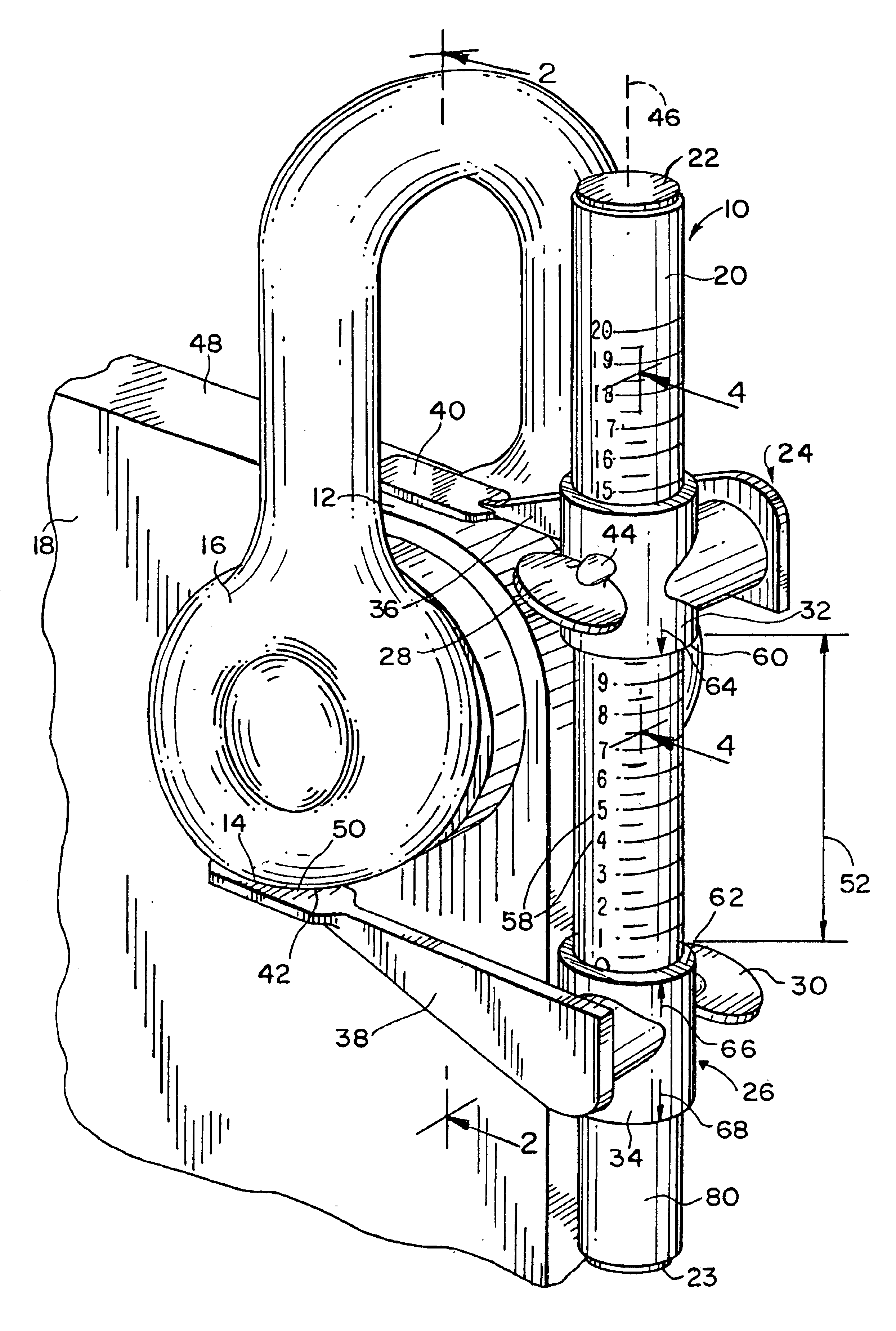
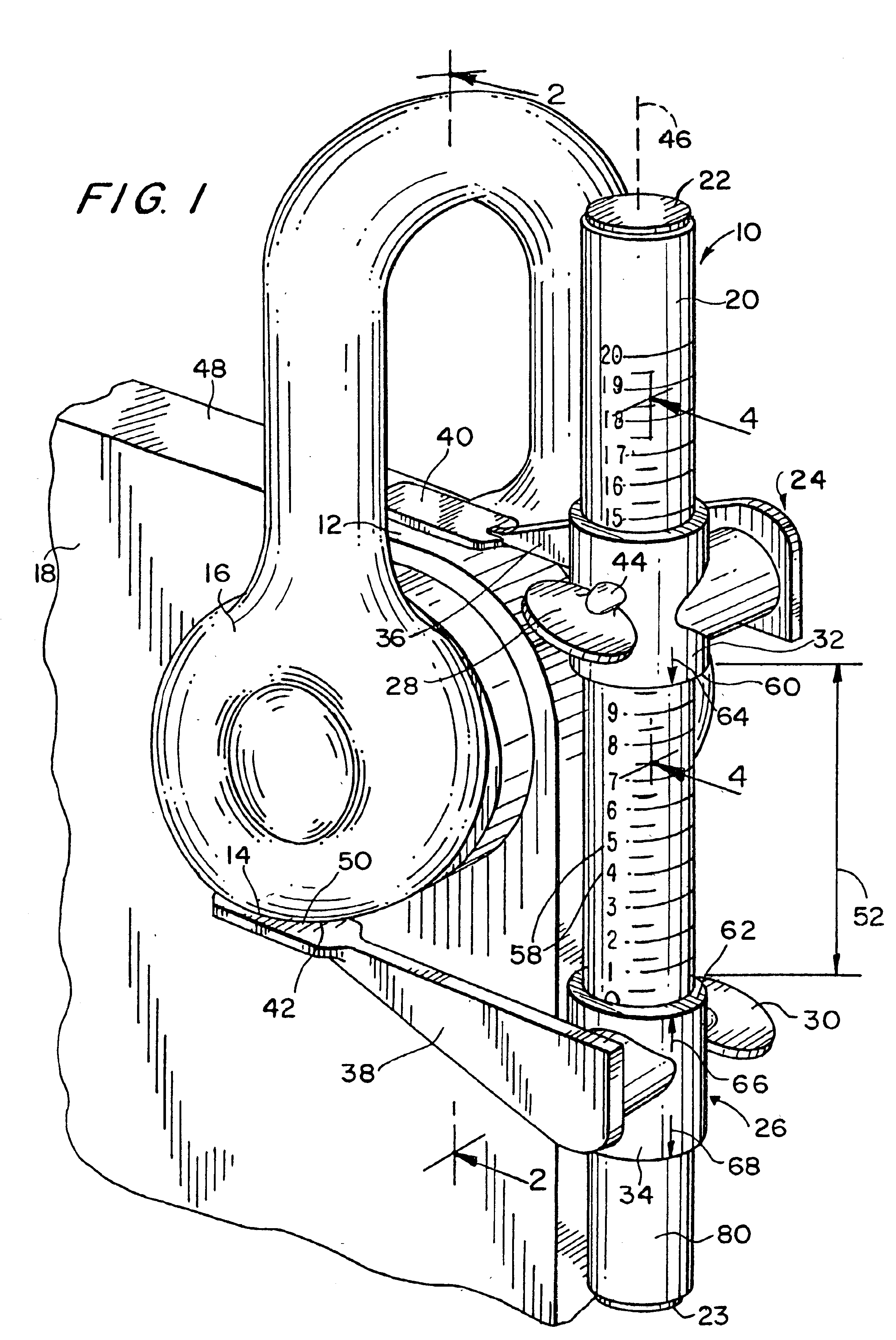
In a first embodiment, with a padeye 18 engaging a shackle 16, shown in FIGS. 1-3, the radius R represents the radius of the padeye 18, the diameter D represents the padeye hole diameter, the depth P represents the half-shackle pin depth, and the radius S represents the shackle palm radius.

For a new padeye 18 coupled to a new shackle 16 illustrated in FIG. 2, with a slight gap 82 present, the references dimension ANEW, is determined by:

ANEW=R−(D / 2)+P+S.

As illustrated in FIG. 3, after some wear has occurred, any pre-existing gap 82 between the padeye and the shackle will have widened to be the gap 84, so the reference dimension AFIELD as measured in the field is determined by positioning the arm portions 36, 38 with respective surfaces 40, 42 of the slidable arms 24, 26 on the shackle 18 and the padeye 16, respectively.

The total combined wear of the padeye 18 and shackle pin from the new condition in FIG. 2 to the worn condition in FIG. 3 can be measured to be:

Total Wear=ANEW−AFIELD

a...

Example

In a second embodiment shown in FIG. 5, with an intermediate chain link 72 engaging either one or two shackles or one or two chain links, such as the two links 70, 74, the intermediate chain link 72 has a chain length L and a chain diameter C. The reference dimension BNEW of a new chain link is determined to be:

BNEW=L−4C.

In the field, the reference dimension BFIELD is measured as shown in FIG. 5, with the arm portions 36, 38 with respective surfaces 40, 42 positioned on the same side of the longitudinal axis 46 of the tube 20, allowing both arm portions 36, 38 to be positioned between the ends of the adjacent chain links and / or shackles.

The total combined wear associated with the chain link is measured to be:

Total Wear=(BNEW−BFIELD) / 2

and the actual wear, as a percentage change from the new condition, can be measured to be:

Actual Wear (%)=100×[BNEW−BFIELD] / 4C.

For example, for a new chain link, the associated dimensional parameters can be L=381 mm. and C=63.5 mm., so the new reference...


PUM


Abstract

A wear measurement device permits reliable and accurate measurements of wear and wear trends for fastening devices used in maritime applications, and on-shore facilities, such as chains, shackles, padeyes, anchor legs, and the like. The device utilizes a pair of arms slidable on a tube and positionable to contact out-of-plane surfaces and provide a direct reading of the distance between the surfaces from a scale containing dimensional indicia on the exposed surface of the supporting tube.

Description

BACKGROUND OF THE INVENTION1. Field of the InventionThis invention is related to measurement devices, and in particular to devices for measuring wear experienced by padeyes, shackles, chains, and other similar elements used in maritime applications and on-shore installations.2. Description of the Related ArtIn maritime industry, fastening devices are used that are typically fabricated of metal; that is, metal elements with rings and / or hooks. Such fastening devices are attached to, and secure other fastening devices and / or portions of ships, barges and boats, for maritime applications using anchors, moorings, and the like for securing a ship to a dock or other facilities. Such fastening devices experience wear from frictional interaction between adjacent and / or abutting portions of the fastening devices, as well as, other eroding or corroding factors and sources such as oxidation, interaction with salt water, pollution, cleaning chemicals, etc. For example, the wear of padeyes, shac...

Claims


Application Information

Patent Timeline
IPC IPC(8): G01B3/20G01B5/14G01B5/16
CPCG01B5/16G01B3/20
Inventor COOKSON, RAYMOND ALEC
Owner SAUDI ARABIAN OIL CO
Why Eureka
Try Eureka