Method for operating a gas and steam turbine system and a corresponding system

a gas turbine and steam turbine technology, applied in the direction of machines/engines, mechanical equipment, transportation and packaging, etc., can solve the problems of inconvenient operation, high cost, and inability to meet the requirements of the system, and achieve the effect of simple operation, low cost and low cos

Inactive Publication Date: 2005-04-05
SIEMENS AG
View PDF11 Cites 20 Cited by
  • Summary
  • Abstract
  • Description
  • Claims
  • Application Information

AI Technical Summary

Benefits of technology

Because of the relatively less complex control and switching systems, a relatively simple mode of operation is, on the one hand, achieved and, in addition, a relatively high level of reliability also. Thi

Problems solved by technology

At low steam pressures, however, such a method requires a large-volume, and under certain circumstances multistage, heating-steam system in the feed-water tank which, in the case of large heating ranges, can endanger a degassing system which is usually located in the feed-water tank.
Particularly in the case of three-pressure installations or circuits, however, this has the substantial disadvantage that an additional, external condensate preheater is required which must be designed for the high pressures and high temper

Method used


Image

  • Method for operating a gas and steam turbine system and a corresponding system
  • Method for operating a gas and steam turbine system and a corresponding system
  • Method for operating a gas and steam turbine system and a corresponding system

Examples


Embodiment Construction

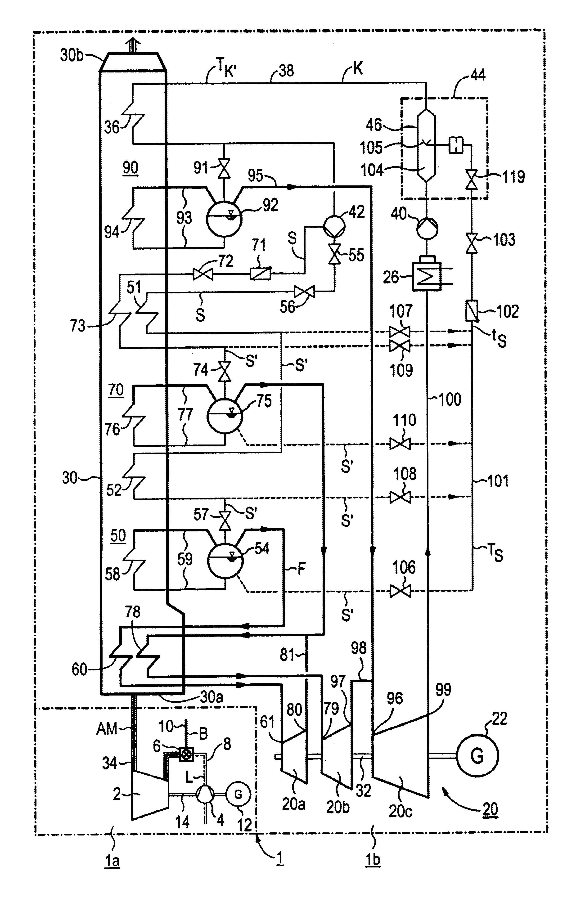
The gas turbine and steam turbine installation 1 shown in the figure includes a gas turbine installation 1a and a steam turbine installation 1b. The gas turbine installation 1a includes a gas turbine 2 with connected air compressor 4 and, connected upstream of the gas turbine 2, a combustion chamber 6, which is connected to a fresh air main 8 of the air compressor 4. A fuel main 10, by which the combustion chamber 6 can be optionally supplied with gas or oil as the fuel B, opens into the combustion chamber 6. This fuel B is burnt, with the supply of compressed air L, to form working fluid or combustion gas for the gas turbine 2. The gas turbine 2 and the air compressor 4, together with a generator 12, are seated on a common turbine shaft 14.

The steam turbine installation 1b comprises a steam turbine 20 with connected generator 22 and, in a water / steam cycle 24, a condenser 26 and a waste-heat steam generator 30 connected downstream of the steam turbine 20. The steam turbine 20 has a...


PUM

PropertyMeasurementUnit
Pressureaaaaaaaaaa

Abstract

In a method of operating a gas turbine and steam turbine installation with a gas turbine which can be operated with both gas and oil, a partial flow of heated feed water is injected into the cold condensate when a change is made from gas operation to oil operation. For this purpose, the installation comprises a mixing device, in which at least one spray head connected to a hot-water main, is arranged for the supply of the partial flow.

Description

FIELD OF THE INVENTIONThe invention generally relates to a method of operating a gas turbine and steam turbine installation or system. In one embodiment, it relates to a method in which the exhaust gas emerging from a gas turbine, which can be operated with both gas and oil, is routed via a waste-heat steam generator whose heating surfaces are connected into the water / steam cycle of a steam turbine having a number of pressure stages. Condensate preheated in the waste-heat steam generator is heated by feed water at a pressure which is high relative to the condensate and is supplied as steam to the steam turbine.BACKGROUND OF THE INVENTIONIn a gas turbine and steam turbine installation or system, the heat contained in the expanded working fluid or exhaust gas from the gas turbine is used for generating steam for the steam turbine connected into the water / steam cycle. In this arrangement, the heat transmission takes place in a waste-heat steam generator or boiler which is connected dow...

Claims


Application Information

Patent Timeline
IPC IPC(8): B01F3/08B01F5/04F01K23/10
CPCB01F3/0865B01F3/088F01K23/106B01F15/026B01F5/0453B01F23/451B01F23/49B01F25/3132B01F35/71805
Inventor SCHWARZOTT, WERNER
Owner SIEMENS AG
Why Eureka
Try Eureka