
Ink jet transfer printing process

Inactive Publication Date: 2005-04-05
3M INNOVATIVE PROPERTIES CO
View PDF72 Cites 13 Cited by
  • Summary
  • Abstract
  • Description
  • Claims
  • Application Information

AI Technical Summary

Benefits of technology

In one aspect, the present invention relates to a method for imparting graphics to substrates, and to products made in accordance with this methodology. In accordance with the method, an image transfer sheet comprising an image receptor layer is coated onto a temporary carrier sheet. The transfer sheet is then imaged by conventional ink jet printing. A substrate or an article containing a substrate, is provided with at least one patch of pressure sensitive adhesive which preferably corresponds in size and shape to the image transfer sheet. The adhesive patch is preferably protected from contact prior to use by a releasable backing sheet. Transfer of the image to the substrate is carried out by removal of the protective backing sheet from the adhesive patch, followed by lamination of the image transfer sheet, image side down, to the adhesive patch. After a

Problems solved by technology

However, flexography, silk screen, and the other printing techniques commonly used by the industry to produce decorative foil balloons are generally limited to large scale production, and do not lend themselves to small scale, customized production of the type required for customized or personalized items.
However, the approach of WO 00 / 11067 (Lang) suffers from a number of serious drawbacks.
Consequently, when a foil balloon is fed through a conventional inkjet printer, it tends to wrap around the drums, rollers and other feeding mechanisms of the printer, thereby causing the printer to jam.
However, this approach suffers from the drawback that such a substrate tends to jam the feeding mechanisms of conventional printers, which are designed for feeding paper sheets of ordinary caliper.
The approach of WO 00 / 11067 (Lang) also assumes that the uninflated balloon can be pressed into a flat or smooth surface suitable for printing, and thus places limitations on the size and geometry of the balloon and on the way that the balloon is compressed for storage or shipping.
Moreover, the approach of WO 00 / 11067 (Lang) is not applicable to inflated balloons.
However, the use of a thermally activated adhesive is a requirement of such systems, since the sheet must pass through a printer without adhering to the feed mechanism.
Since foil balloons are temperature sensitive and tend to distort and shrivel at elevated temperatures, this requirement precludes the use of this technique for transfer to foil balloons.
However, this approach suffers from the infirmities noted above in that the use of a thermally activated adhesive precludes its use on temperature sensitive substrates such as foil balloons.
However, this approach is undesirable in that the printing of the image on the non-adsorbent medium allows the ink to coalesce before the image is imparted to the target substrate, thereby resulting in blurring of the image and an overall reduction in image quality.
Moreover, any lateral motion of the non-adsorbent medium during the image application process will cause the image to be smeared.
Hence, this approach is not very user friendly and is not suitable where high image quality is desirable.
As with other wet transfer techniques, however, this procedure is prone to smudging of the image during the transfer process.

Method used


Image

  • Ink jet transfer printing process
  • Ink jet transfer printing process
  • Ink jet transfer printing process

Examples


example 1

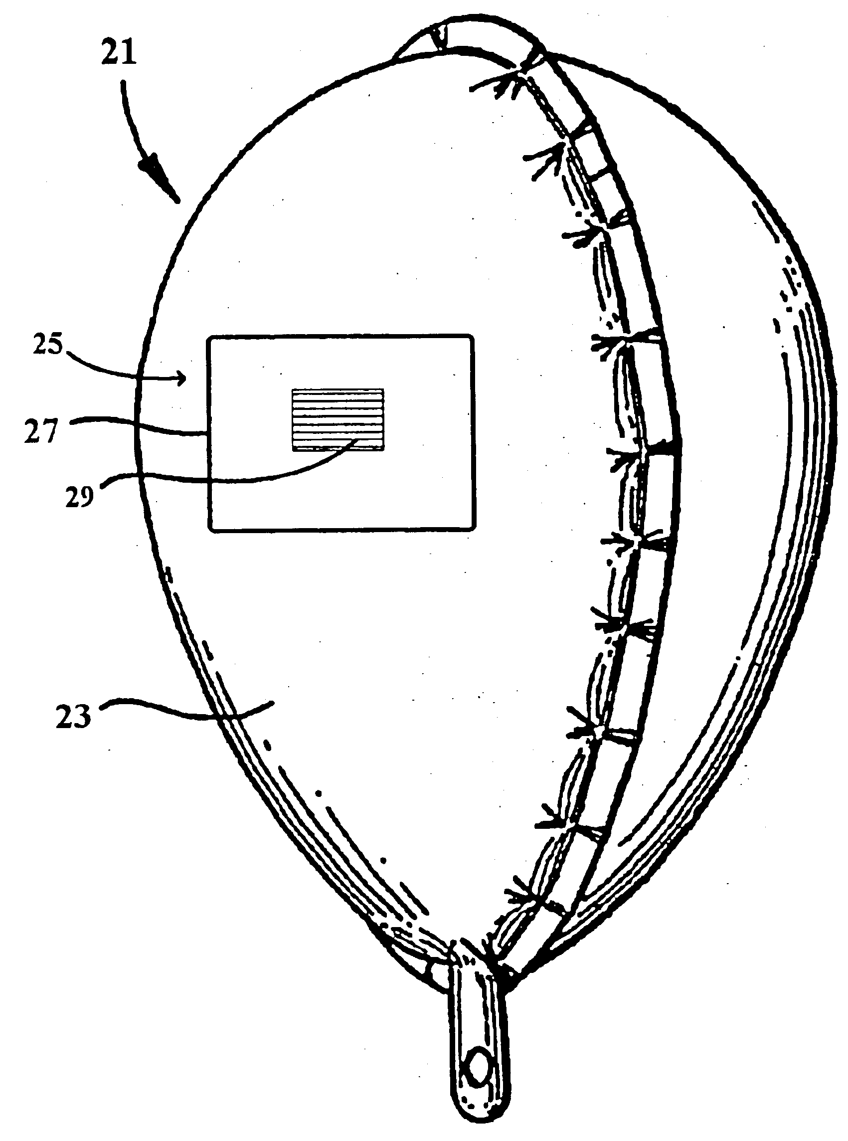
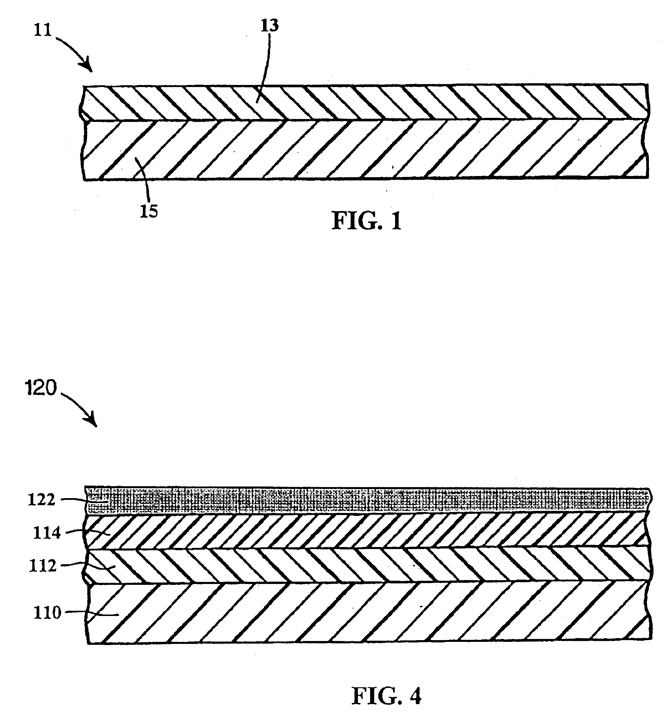
This example illustrates the preparation of an image transfer sheet in accordance with the present invention.

A solution of the following components was coated onto a temporary carrier sheet of 100 microns thick unprimed polyethylene terephthalate film and dried using blown air at 160° C. The coating weight of the dried layer was 10.7 g per square meter.

Coating composition (percent by weight):water 90%polyethylene oxide (200,000 molecular weight)0.8%hydroxypropylmethyl cellulose5.5%colloidal hydrated alumina2.4%sorbitol1.0%mordant10.3%1The mordant is the compound identified as P. 134-Cl in U.S. Pat. No. 5,342,688 (Kitchin et al.).

The adhesion of the dried coating to the polyethylene terephthalate was sufficient that the coating remaining adhered during normal handling, including cutting of the composite into 8.5×11 sheets, but the coating was readily removed as an into layer by application of a short length of 3M SCOTCH™ brand MAGIC™ tape to the surface of the coating, followed by r...

example 2

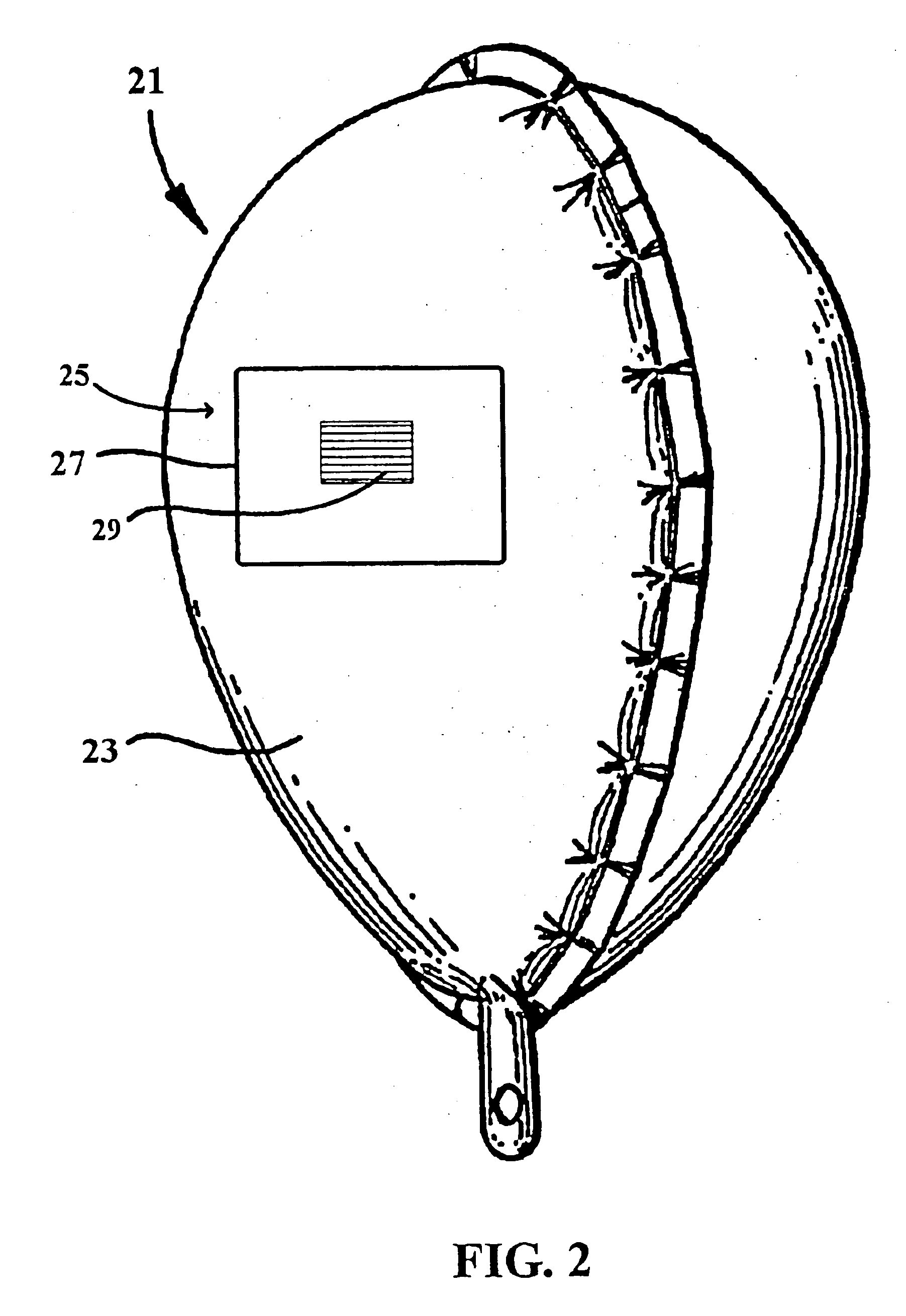
This example illustrates the preparation of an image receptive balloon.

An 18 inch diameter aluminized foil balloon, manufactured by Anagram International Inc. of Minneapolis, Minn. was laid out on a fist surface. An 8.5×11 inch rectangular sheet of 3M SCOTCH™ brand 9457 Hi-tack Acrylic laminating Adhesive was adhered to the exposed side of the balloon, using firm hand pressure. The releasable backing sheet was left in place covering the adhesive.

example 3

This example illustrates preparation and transfer of an image in accordance with the present invention.

An 8.5×11 inch sample of image transfer sheet, prepared as described above, was imaged on the ink absorptive layer side with a color test pattern using a Hewlett-Packard 2500C ink jet printer. The mirror image option was selected on the printer. The printed image was allowed to dry for five minutes. The releasable backing sheet was removed from the balloon of EXAMPLE 2. The image side of the image transfer sheet was pressed into contact with the adhesive patch on the balloon using firm hand pressure. The releasable backing sheet was then peeled away from the image and discarded. A high-quality image remained in place on the balloon.


PUM

PropertyMeasurementUnit
Weightaaaaaaaaaa
Pressureaaaaaaaaaa
Frequencyaaaaaaaaaa

Abstract

A method is provided for imparting images created with an inkjet printer to substrates. In accordance with the method, an image is imparted to an image receiving layer releasably disposed on a carrier sheet. An article can be provided, which is equipped with an adhesive patch on its surface. The image receiving layer is then brought into contact with the adhesive patch and, the carrier sheet is removed, thereby imparting an image to the substrate.

Description

FIELD OF THE INVENTIONThe invention relates generally to methods for imparting graphics to a substrate, and in particular to methods for imparting graphics to low rigidity substrates.BACKGROUND OF THE INVENTIONIn recent years, foil balloons have grown in popularity for festive occasions in comparison with traditional latex balloons. Foil balloons, unlike latex balloons, may be manufactured with a decorative, metallized finish, and are readily printed during manufacture with colorful graphics using conventional methods such as flexography or silkscreen. Foil balloons of various designs are currently available at most greeting card stores.The greeting card industry has shown a strong trend as of late toward customization. Thus, for example, many greeting card stores feature equipment that allows patrons to produce customized greeting cards on the premises. This interest has extended to other items sold by the industry, including decorative foil balloons. However, flexography, silk scr...

Claims


Application Information

Patent Timeline
IPC IPC(8): B41C1/00B41F1/16B41F1/00B41C1/06B41M3/12B41M5/03B41M5/035B41M5/52B44C1/17
CPCB44C1/1704B41M5/52Y10T428/24802
Inventor KITCHIN, JONATHAN P.CARLS, JOSEPH CLARKEVANS, DWIGHT LAMARAUSTIN, STEVEN RICHARD
Owner 3M INNOVATIVE PROPERTIES CO
Learn More