

Electromagnetic valve
a technology of electromagnetic valves and valve bodies, applied in the direction of magnetic bodies, fluid pressure control, instruments, etc., can solve the problems of affecting the operation of electromagnetic valves. the effect of reducing the operation noise of electromagnetic valves
- Summary
- Abstract
- Description
- Claims
- Application Information
AI Technical Summary
Benefits of technology
Problems solved by technology
Method used
Image

Examples
embodiment 1
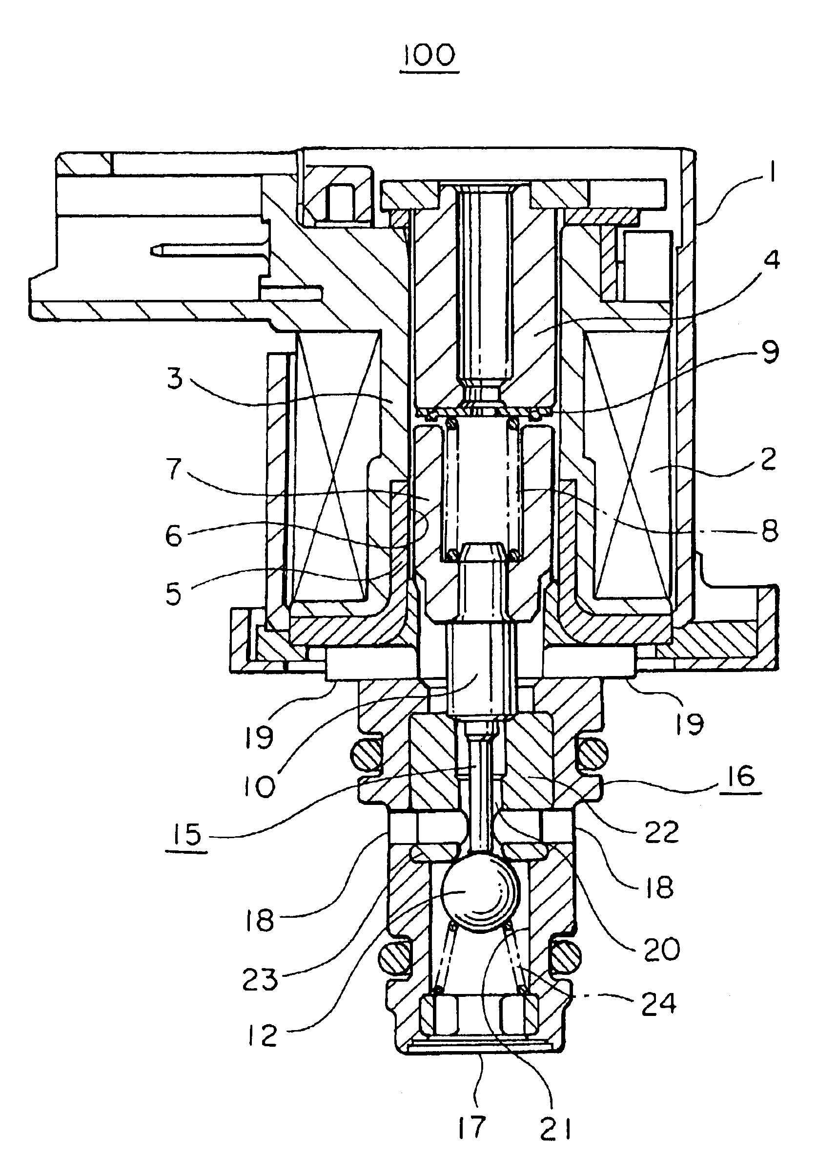
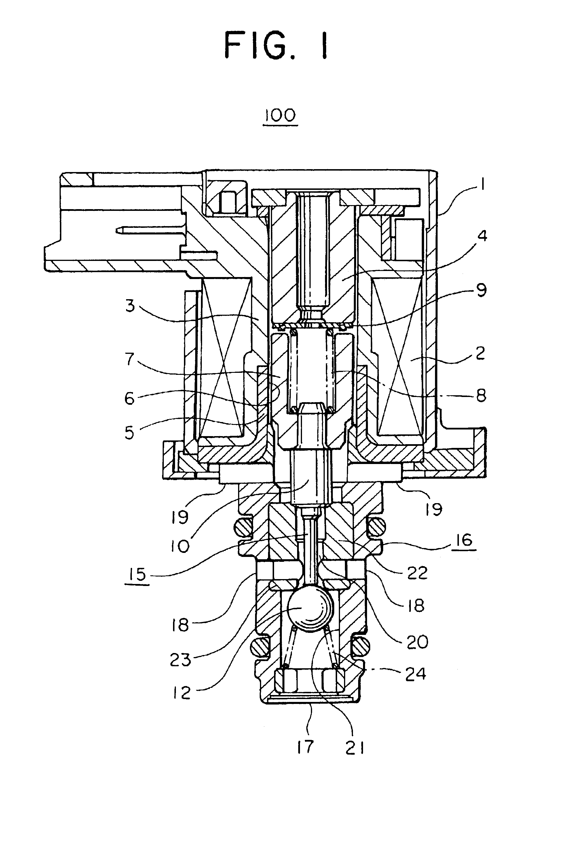
FIG. 1 is a sectional view of the electromagnetic valve according to a first embodiment of the present invention. Referring to the figure, the electromagnetic valve denoted generally by reference numeral 100 is comprised of a case 1 formed of a magnetic material and serving for armoring the electromagnetic valve 100, a coil 2 wound in a cylindrical shape and housed within the case 1, a bobbin 3 formed of a resin material substantially in a spool-like shape, having an outer peripheral surface around which the coil 2 is wound and a longitudinal cylindrical through-hole at the center thereof, a cylindrical thick core 4 fixedly secured to the case 1 at one end and having other end portion extending to a mid portion of the above-mentioned longitudinal through-hole formed in the bobbin 3, a plate 5 formed of a magnetic material and having a cylindrical portion fit into the through-hole of the bobbin 3 in opposition to the fixed core 4 and a disk-like portion extending radially from the lo...
embodiment 2
FIG. 8 is a view showing the shape of a spacer employed in the electromagnetic valve according to a second embodiment of the present invention. FIG. 9 is an enlarged view showing a portion of the electromagnetic valve in the vicinity of the spacer in the state in which the electromagnetic valve is electrically energized. In the electromagnetic valve according to the instant embodiment of the invention, the protrusion provided on the spacer denoted by numeral 29 in the instant embodiment is implemented in the form of a circular boss array in which six circular boss portions 29a are discretely formed in the first or front surface of the spacer 29 on the side of the plunger 7 with equidistance therebetween in a circumferential direction, as can be seen in FIG. 8. On the other hand, in the second or rear surface of the spacer 29 located adjacent to the fixed core 4, there are formed six dimple portions 29b at the positions which correspond to those of the boss portions 29a, respectively...
embodiment 3
FIG. 10 is a view showing the shape of a spacer employed in the electromagnetic valve according to a third embodiment of the present invention. FIG. 11 is an enlarged view showing a portion of the electromagnetic valve in the vicinity of the spacer in the state where the electromagnetic valve is electrically energized. FIG. 12 is an enlarged view showing a portion of the electromagnetic valve in the vicinity of the spacer in the state where the electromagnetic valve is electrically deenergized. In the electromagnetic valve according to the instant embodiment of the invention, the spacer denoted by reference numeral 39 is implemented in the form of a washer waved in the circumferential direction. The waved washer may be the one that is conventionally employed when elasticity is to be imparted to the washer. The waved washer can be manufactured at low cost.
By implementing the spacer 39 in the form of the waved washer as mentioned above, the spacer 39 is imparted with elasticity in the...
PUM
 Abstract
Description
Claims
Application Information