Inkjet printhead

a technology of inkjet printing and nozzles, applied in printing and other directions, can solve the problems of cumbersome process of forming minute structures of ink channels and nozzles, high cost of inkjet printing heads, etc., and achieve good thermal contact

Inactive Publication Date: 2005-04-05
OCE TECH
View PDF13 Cites 3 Cited by
  • Summary
  • Abstract
  • Description
  • Claims
  • Application Information

AI Technical Summary

Benefits of technology

It is an object of the present invention to provide an ink jet printhead, which can be manufactured at low costs and in which the ink channels can be formed with reproducible high accuracy.
As a result, it is not necessary to form the comparatively large volume of the ink reservoir in a time-consuming etching process, and the rather bulky member of the printhead in which the ink reservoir is formed can be manufactured at low costs by molding, sintering or machining a rather inexpensive material such as graphite or ceramic in a relatively grainy form. Only the comparatively small volume of the channel plate is made from expensive materials such as silicon, fine grain graphite, ceramics, etc., in which the fine structures of the ink channels, and, as the case may be, the nozzles, can be formed with high accuracy in an etching or mechanical process in which only a small amount of material has to be removed. Thus, not only the costs for the material but also the costs for the manufacturing process can be reduced significantly.
In a preferred design of an ink jet printhead the nozzles are arranged in two parallel rows. In this case, the ink channels associated with the respective rows of nozzles can either be formed in opposite surfaces of a single channel plate or can be formed in the surfaces of separate channel plates sandwiched with a portion of the ink reservoir defining member. In the latter case, a large area of contact between the channel plates and the ink reservoir defining member is achieved, and, accordingly, there is a good thermal contact between the ink reservoir defining member and the channel plates, which is particularly advantageous in case of a hot-melt printhead in which the ink contained in the ink reservoir and the ink channels needs to be liquefied by heating.

Problems solved by technology

In this case, however, the ink channels must be cut into the surface of the channel plate, and the process of forming the minute structures of the ink channels and nozzles becomes more cumbersome or a graphite with a very small grain size must be used which makes the inkjet printhead expensive.

Method used


Image

  • Inkjet printhead
  • Inkjet printhead

Examples


Embodiment Construction

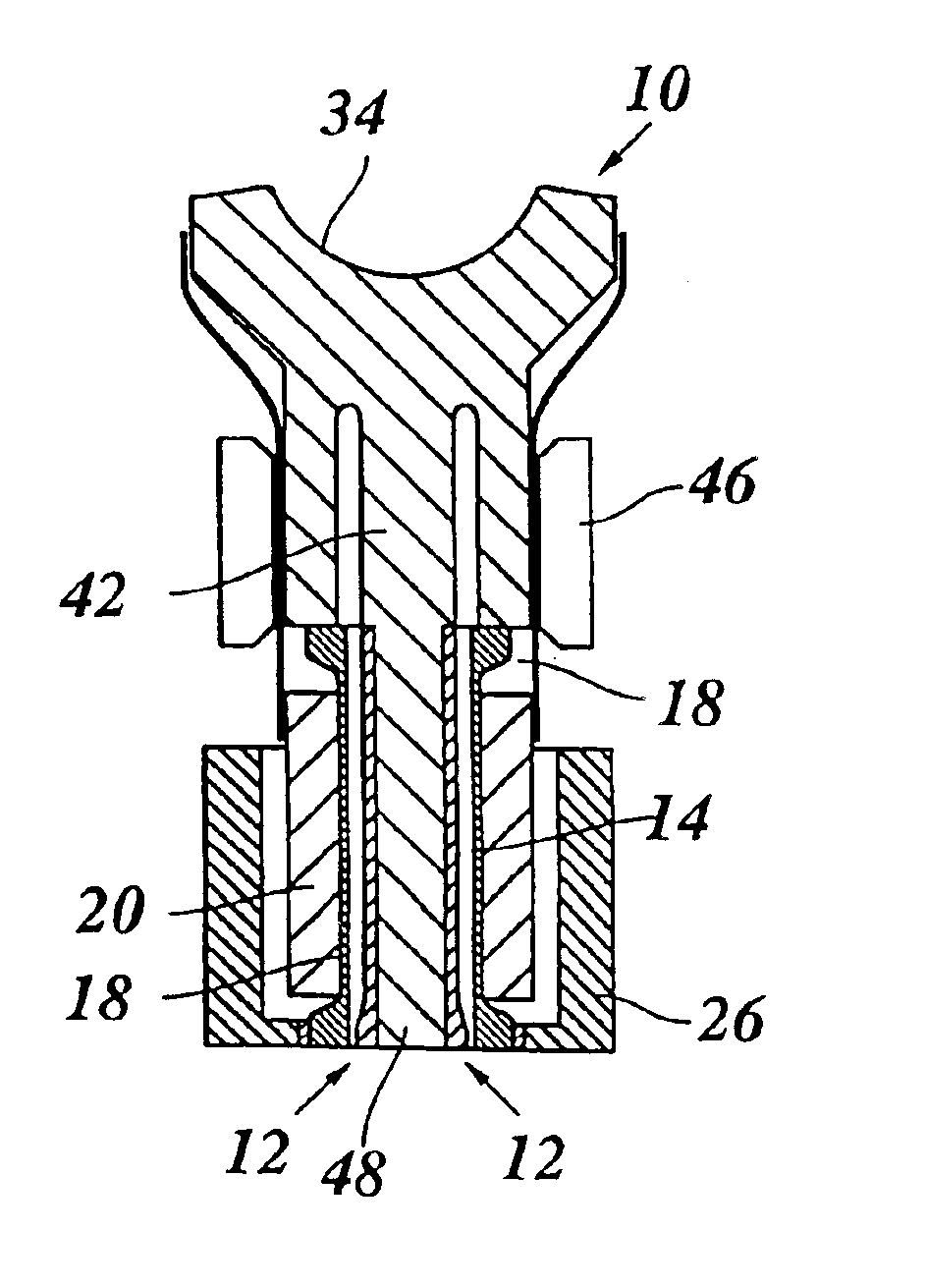
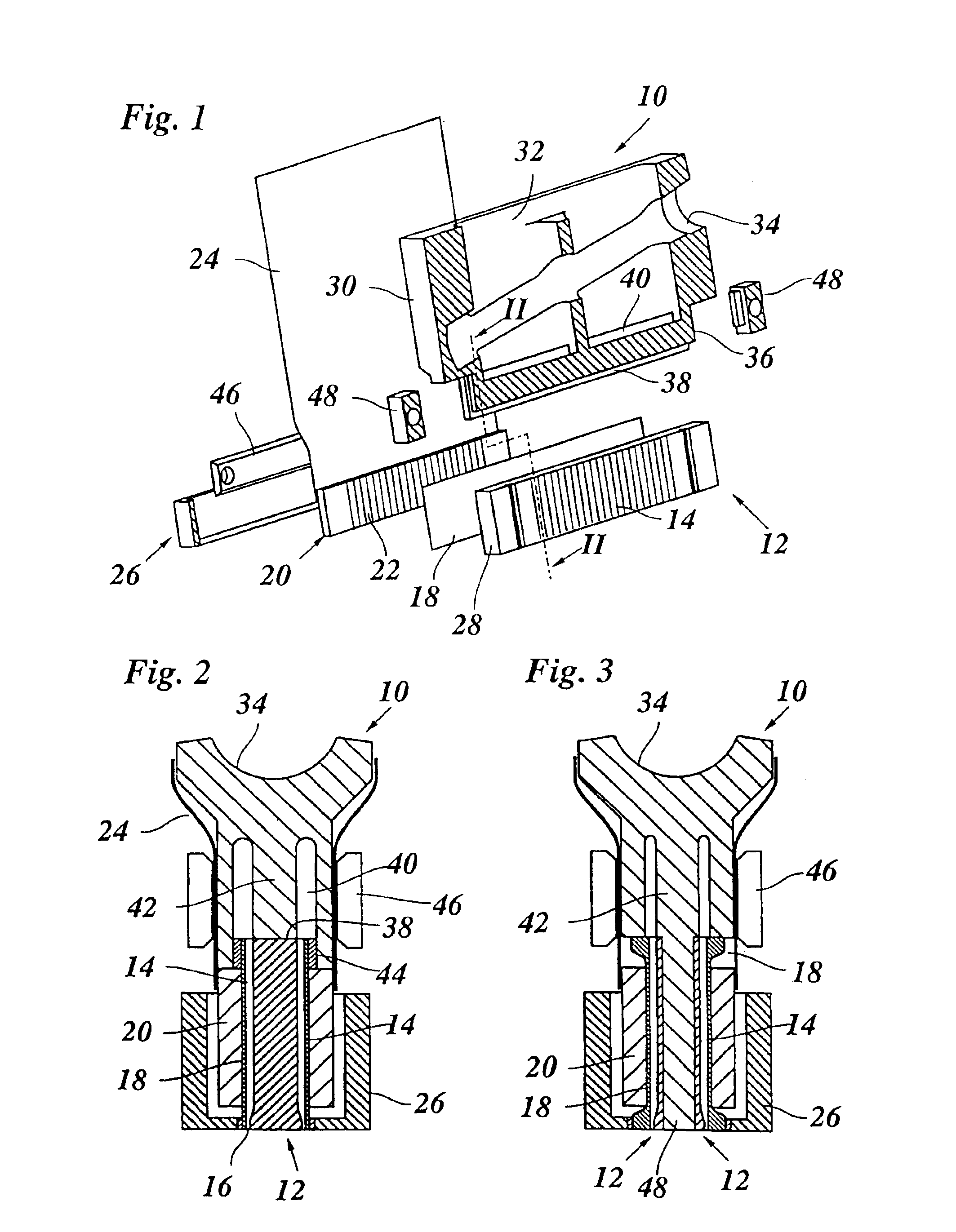
As is shown in FIGS. 1 and 2, an ink jet printhead according to the present invention has a symmetric structure and comprises as main components a base plate 10 made of graphite or ceramic and a channel plate 12 made of an etchable material, preferably a semiconductor material such as silicon. The channel plate 12 has opposite lateral surfaces in which a plurality of parallel, vertically extending ink channels 14 are formed by etching. Each ink channel 14 is converged to form a nozzle 16 (FIG. 2) at the lower end thereof and is open at its top end. The open lateral sides of the ink channels 14 and the nozzles 16 are covered by a flexible sheet 18 made of the same material as the channel plate 12 and firmly bonded thereto. An actuator block 20 is bonded to the outer surface of each sheet 18. The actuator block 20 is made of a piezoelectric ceramic material and has a comb-like structure forming a plurality of parallel, vertically extending piezoelectric fingers 22 and is provided with...


PUM


Abstract

An ink jet printhead comprising a channel plate having a plurality of ink channels etched into at least one surface thereof, actuators respectively associated with each of the ink channels for pressurizing ink contained in the ink channels, and means defining an ink reservoir communicating with the ink channels, wherein said ink reservoir is defined by a base member made of a material different from that of the channel plate.

Description

BACKGROUND OF THE INVENTIONThe present invention relates to an ink jet printhead comprising a channel plate having a plurality of ink channels etched into at least one surface thereof, actuators respectively associated with each of the ink channels for pressurizing ink contained in the ink channels, and means defining an ink reservoir communicating with the ink channels. The present invention also relates to a method for manufacturing such a printhead.An example of a conventional printhead of this type is described in EP-A-0 671 372. The ink channels are arranged side-by-side in one surface of the channel plate and extend in parallel to one another with narrow spacings formed therebetween. Each ink channel converges into a nozzle at one end thereof, so that an array of nozzles is formed, by which a plurality of ink droplets can be expelled simultaneously by energizing the actuators respectively associated with the ink channels. For a high-resolution printer, it is required that the ...

Claims


Application Information

Patent Timeline
Patent Type & Authority Patents(United States)
IPC IPC(8): B41J2/14B41J2/055B41J2/045B41J2/16
CPCB41J2/14274B41J2/14233
Inventor HOLLANDS, PETER JOSEPHELLENKAMP, HENDRIK WILLEM
Owner OCE TECH
Why Eureka
Try Eureka